
Homework Answers
Add Answer to:
A beam with simple supports as shown below has external loading of three point loads and...
4. For the beam and loading shown, draw the shear force and bending moment diagrams and...
 4. For the beam and loading shown, draw the shear force and bending moment diagrams and determine the maximum bending and shear force and their locations. 20 KN 40 KN B D 250 mm |--2.5 m- 3m-4-2 m 80 mm 5. For the beam and loading shown, draw the shear force and bending moment diagrams and determine the maximum bending and shear force and their locations. 50 KN
A cantilever beam supports the applied loads and moments as shown. (a) Calculate the support reactions....
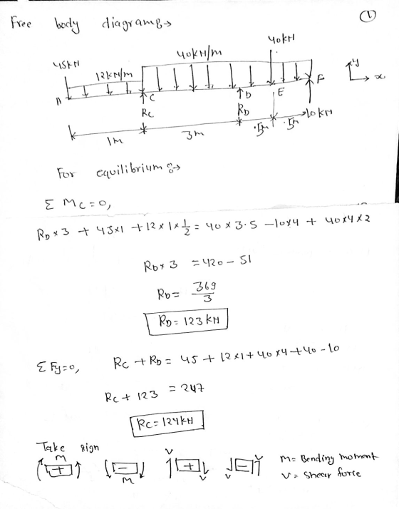
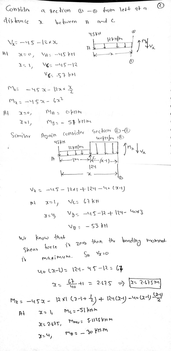
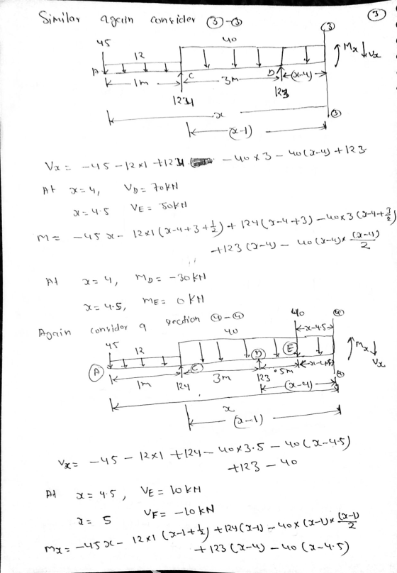
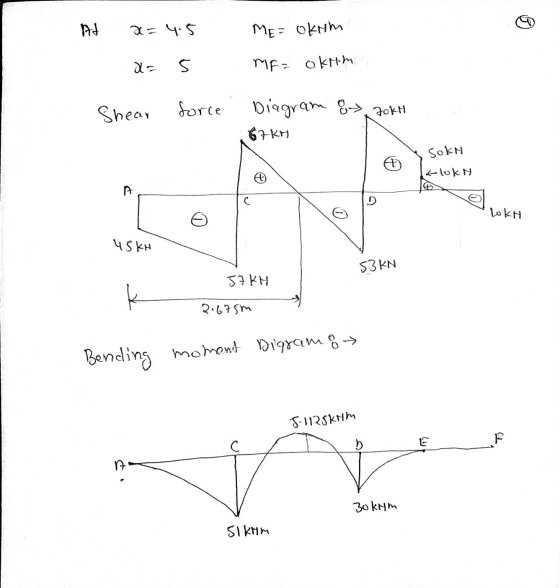
 A cantilever beam supports the applied loads and moments as shown. (a) Calculate the support reactions. (b) Use the graphical method to construct the shear-force and bending moment diagrams for the beam. Also label the values of shear-force and bending=moment at all key points. 30 kN/m 25 kN 12 kN/m 80 kN.m х A В C D E F 1 m 3 m 1 m 1 m 1 m
A cantilever beam supports the loads shown. The cross-sectional dimensions of the shape are also shown....
 A cantilever beam supports the loads shown. The cross-sectional dimensions of the shape are also shown. Assume mm, by - 85 mm, 5 mm, 9 mm. Determine - 0.5 m, P. - 4.0 kN, Pg - 7.5 kN, Pe-2.0 kN, -85 (a) the maximum vertical shear stress. (b) the maximum compression bending stress. (c) the maximum tension bending stress. See the coordinate system for the beam in the problem figure with the origin of the x axis at the feed...
50 kN 40 kN/m Q1: For the overhanging beam shown below, draw the shear force and...
 50 kN 40 kN/m Q1: For the overhanging beam shown below, draw the shear force and bending moment diagrams. Write the equations for the shear force and the bending diagrams as needed. For bonus points sketch the deformation shape (elastic shape of the beam under the given loads). Hint: A is pin support, and B is roller. 4 m 2 m
The beam is loaded as shown in the diagram below. The beam is uniformly loaded at...
 The beam is loaded as shown in the diagram below. The beam is uniformly loaded at 3 kN/m for the length of 4 m from B. The beam also has two point loads, 4 KN at 2 m from A and 3 KN at 3 m from B. 2 KN 3 KN 3KN/m A 2 m 2 m 11 m 3 m Fig. Q2 Draw a shear force and bending moment diagram. Also determine the location of maximum bending moment...
1. (28 pts) A cantilever beam is subjected to the loads as shown in the figure....
 1. (28 pts) A cantilever beam is subjected to the loads as shown in the figure. Va) Draw a free-body diagram and determine the supports at point 0. b) Draw shear and moment diagrams and find the values at key points (i.e. x = 0, 6 and 10 ft). If possible, please show your calculations. c) Find shear force V(x) and bending moment M(x) for () <x<6 ft. 12 10 kip 2 kip/ft skip سے 40 kip.lt 611 4 11...
QUESTION 2 [30 Marks) The framed structure shown in Figure 2 has simple supports (i.e. is...
 QUESTION 2 [30 Marks) The framed structure shown in Figure 2 has simple supports (i.e. is free to rotate) at joints A and G. Members AC and GE are vertical, while CE and EH are horizontal. There is an internal moment release at joint C. A uniformly distributed load of 5 kN/m is applied between D and E, and another uniformly distributed load of 4 kN/m is applied between F and G as shown. There is also a horizontal point...
Question AT For the beam and loading shown in Figure Al: - a. Determine the support...
 Question AT For the beam and loading shown in Figure Al: - a. Determine the support reactions b. Draw the shear and bending moment diagrams c. Determine the maximum absolute value of shear force and bending moment. 30 kN/m 60 kN C D K-2m-imta2m- Figure A1
Required Information For the beam shown, find the reactions at the supports and plot the shear-force...
 Required Information For the beam shown, find the reactions at the supports and plot the shear-force and bending-moment diagrams. V1 = 2 KN and V2 = 4 kN. NOTE: This is a multi-part question. Once an answer is submitted, you will be unable to return to this part. Vi V2 1.2 min А R2 Determine the values of the moments My, M2, and M3 In kNm. Provide values at all key points shown in the given shear-force and bending-moment diagrams....
2. For the beam and loading shown in the following figure: (a) find all the reaction...
 2. For the beam and loading shown in the following figure: (a) find all the reaction forces, (b) draw the shear and bending moment diagrams and (c) determine the maximum absolute value of the shear and the bending moment. 25 kN m 40 kN 401N 0.61 1.S 0.6 m
 4. For the beam and loading shown, draw the shear force and bending moment diagrams and determine the maximum bending and shear force and their locations. 20 KN 40 KN B D 250 mm |--2.5 m- 3m-4-2 m 80 mm 5. For the beam and loading shown, draw the shear force and bending moment diagrams and determine the maximum bending and shear force and their locations. 50 KN
 A cantilever beam supports the applied loads and moments as shown. (a) Calculate the support reactions. (b) Use the graphical method to construct the shear-force and bending moment diagrams for the beam. Also label the values of shear-force and bending=moment at all key points. 30 kN/m 25 kN 12 kN/m 80 kN.m х A В C D E F 1 m 3 m 1 m 1 m 1 m
 A cantilever beam supports the loads shown. The cross-sectional dimensions of the shape are also shown. Assume mm, by - 85 mm, 5 mm, 9 mm. Determine - 0.5 m, P. - 4.0 kN, Pg - 7.5 kN, Pe-2.0 kN, -85 (a) the maximum vertical shear stress. (b) the maximum compression bending stress. (c) the maximum tension bending stress. See the coordinate system for the beam in the problem figure with the origin of the x axis at the feed...
 50 kN 40 kN/m Q1: For the overhanging beam shown below, draw the shear force and bending moment diagrams. Write the equations for the shear force and the bending diagrams as needed. For bonus points sketch the deformation shape (elastic shape of the beam under the given loads). Hint: A is pin support, and B is roller. 4 m 2 m
 The beam is loaded as shown in the diagram below. The beam is uniformly loaded at 3 kN/m for the length of 4 m from B. The beam also has two point loads, 4 KN at 2 m from A and 3 KN at 3 m from B. 2 KN 3 KN 3KN/m A 2 m 2 m 11 m 3 m Fig. Q2 Draw a shear force and bending moment diagram. Also determine the location of maximum bending moment...
 1. (28 pts) A cantilever beam is subjected to the loads as shown in the figure. Va) Draw a free-body diagram and determine the supports at point 0. b) Draw shear and moment diagrams and find the values at key points (i.e. x = 0, 6 and 10 ft). If possible, please show your calculations. c) Find shear force V(x) and bending moment M(x) for () <x<6 ft. 12 10 kip 2 kip/ft skip سے 40 kip.lt 611 4 11...
 QUESTION 2 [30 Marks) The framed structure shown in Figure 2 has simple supports (i.e. is free to rotate) at joints A and G. Members AC and GE are vertical, while CE and EH are horizontal. There is an internal moment release at joint C. A uniformly distributed load of 5 kN/m is applied between D and E, and another uniformly distributed load of 4 kN/m is applied between F and G as shown. There is also a horizontal point...
 Question AT For the beam and loading shown in Figure Al: - a. Determine the support reactions b. Draw the shear and bending moment diagrams c. Determine the maximum absolute value of shear force and bending moment. 30 kN/m 60 kN C D K-2m-imta2m- Figure A1
 Required Information For the beam shown, find the reactions at the supports and plot the shear-force and bending-moment diagrams. V1 = 2 KN and V2 = 4 kN. NOTE: This is a multi-part question. Once an answer is submitted, you will be unable to return to this part. Vi V2 1.2 min А R2 Determine the values of the moments My, M2, and M3 In kNm. Provide values at all key points shown in the given shear-force and bending-moment diagrams....
 2. For the beam and loading shown in the following figure: (a) find all the reaction forces, (b) draw the shear and bending moment diagrams and (c) determine the maximum absolute value of the shear and the bending moment. 25 kN m 40 kN 401N 0.61 1.S 0.6 m
Most questions answered within 3 hours.
-
a
62 kg sprinter, started from resr, runs 47 m in 7 s at a constant...
asked 4 seconds from now -
For python 3.7. This should only be a few lines if any, but for
some reason...
asked 10 minutes ago -
what is IoT? How is it being used today? How will it be used in
the...
asked 23 minutes ago -
Please answer the four questions below.
1. If you were going to test a method that...
asked 38 minutes ago -
Provide two or three examples of support he uses to reinforce
his arguments?
The Alienation of...
asked 46 minutes ago -
QUESTION 1
Why do we see terms with multiple names in the database
community?
Consistency is...
asked 41 minutes ago -
In a titration experiment, 11.5 mL of 0.400 M H2SO4 neutralized
48.0 mL of NaOH. What...
asked 45 minutes ago -
A shot-putter throws the shot with a horizontal velocity of 10
m/s and a
vertical velocity...
asked 1 hour ago -
Mildred sells industrial-sized refrigeration units. Her
prospective buyer's face looks tense, and his forehead is wrinkled....
asked 1 hour ago -
Clark Heter is an industrial engineer at Lyons Products. He
would like to determine whether there...
asked 2 hours ago -
3. Use a text editor to create a comma-delimited file of user
IDs and passwords. Revise...
asked 1 hour ago -
Jensen and Associates has a projected balance
sheet that includes the following accounts. What is the...
asked 1 hour ago