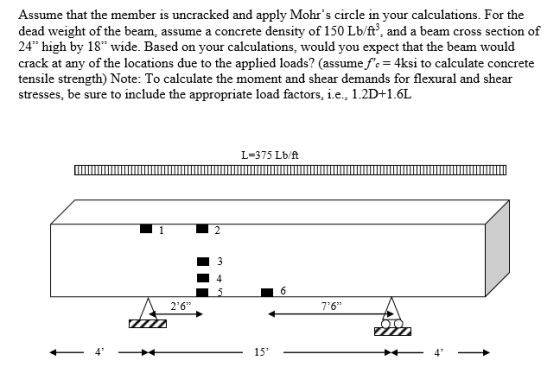
For the beam shown below, determine the flexural stresses, shear stresses, principal stresses,
and the angle to the principle stress plane at the locations shown. Can you solve Location one and 4 first< then as many other as you can please?
Locations 1 and 2 are at the top of the beam, while locations 5 and 6 are at the bottom.
Location 3 is at the beam mid-height, while location 4 is midway between locations 3 and 5.
Homework Answers


Add Answer to:
For the beam shown below, determine the flexural stresses, shear
stresses, principal stresses,
and the angle...
An elevation of a concrete frame is shown below. A superimposed dead load of 200 lb/ft and a live load of 600 lb/ft are to be supported in addition to the beam self-weight. The beam's cross-...
 An elevation of a concrete frame is shown below. A superimposed dead load of 200 lb/ft and a live load of 600 lb/ft are to be supported in addition to the beam self-weight. The beam's cross- section is shown as well. The weight density of reinforced concrete is 150 lbs/eu. ft. Use 1.2D+1.6L as your load combination. Use ACI moment coefficients and statics, as appropriate, to provide the Mu values for points A, B, C, and D. 48 5" 15"...
(a) Determine the maximum compressive and tensile normal stresses in the A-36 structural steel beam shown...
 (a) Determine the maximum compressive and tensile normal
stresses in the A-36 structural steel beam shown and define their
locations (location along the beam and on the cross section). (b)
Determine the deflection of point B using the double
integration method. The height of the cross section shown (in the
y-direction) is 5 inches and width (in the
z-direction) is 10 inches, and the average thickness
throughout is 0.5 inches. (Use elastic properties for all
calculations)
ANSWER: (a) max tensile...
(a) Determine the maximum compressive and tensile normal
stresses in the A-36 structural steel beam shown and define their
locations (location along the beam and on the cross section). (b)
Determine the deflection of point B using the double
integration method. The height of the cross section shown (in the
y-direction) is 5 inches and width (in the
z-direction) is 10 inches, and the average thickness
throughout is 0.5 inches. (Use elastic properties for all
calculations)
ANSWER: (a) max tensile...
The beam is simply supported. Problem 3. (30 points) A wooden beam is composed of a...
 The beam is simply supported.
Problem 3. (30 points) A wooden beam is composed of a 2 x8" (1.5"x7.25") top flange and a 3"x10 (2.5"x9.25") web to form a T section. Assume that the two members are glued together. L-16 ft. (a) For a uniform dead load of 20 lb/ft over the entire beam span and a uniform live load of 80 lb/ft over the left half of the span, draw the shear and moment diagrams. (b) Determine the cross-sectional...
The beam is simply supported.
Problem 3. (30 points) A wooden beam is composed of a 2 x8" (1.5"x7.25") top flange and a 3"x10 (2.5"x9.25") web to form a T section. Assume that the two members are glued together. L-16 ft. (a) For a uniform dead load of 20 lb/ft over the entire beam span and a uniform live load of 80 lb/ft over the left half of the span, draw the shear and moment diagrams. (b) Determine the cross-sectional...
Based on tributary load analysis, the dead and live loads, wd and wų, respectively, acting on...
 Based on tributary load analysis, the dead and live loads, wd and wų, respectively, acting on a beam in a vertical load resisting system are shown below. The concrete is normalweight with compressive strength f=5000 psi. Note that the given dead load includes the self-weight of the beam and slab. Section wp=1.2 kip/ft, wu=1.5 kip/ft be-45 inch 5 inch 1 30 inch B A 10 inch In=10 ft 1. Design and detail the beam for positive flexure at section A....
23. For the concrete cantilever beam shown below (L=8 ft), draw the proper location and details for the flexural reinfo...
 23. For the concrete cantilever beam shown below (L=8 ft), draw the proper location and details for the flexural reinforcement of area, As, on the elevation (including connection at support) and cross section. Assume that 3 #8's are used for flexural reinforcement with 2-leg #4 stirrups for shear (spaced at 6 in on center) and 1.5-in cover (over the stirrups). [2 PT] Concentrated load height, h-16 in width, b-12 in; f' 5000 psi Support Elevation Cross Section 24. [9 PT]...
1. For the overhanging beam in the figure below, determine the maximum shear stress, the maximum...
 1. For the overhanging beam in the figure below, determine the maximum shear stress, the maximum tensile stress, and the maximum compressive stress in the beam due to the loading shown. 300 lb/ft 6 in. 1 in. 4 ft 10 ft 1 in. 2 in. Section INSTRUCTIONS For PROBLEM do the following steps: 1. Show ALL your work 2. Draw appropriately labeled FBDs 3. Use appropriate segments to develop expressions for the shear force and bending moment. diagrams in a...
4. Determine the flexural strength (фМп) and shear strength (OVn) of the given section below. The RC beam in Engineering Building is reinforced with 4#10 for tensile reinforcement at the bottom,...
 4. Determine the flexural strength (фМп) and shear strength (OVn) of the given section below. The RC beam in Engineering Building is reinforced with 4#10 for tensile reinforcement at the bottom, 2#4 for compressive reinforcement at the top, and stirrups with #3@ 9" on center. (fc 6 ksi, fy 60 ksi for top and bottom reinforcement, and fyt -40 ksi for stirrups): Case 1: t- 3 in (20 points) and Case 2: t- 10 in (20 points) . 14" 6...
A 15-ft solid concrete cantilever beam with a rectangular cross-section is shown below. It supports a...
 A 15-ft solid concrete cantilever beam with a rectangular cross-section is shown below. It supports a load w = 2,150 lb/ft. The concrete has a tensile strength of 650 psi and a compressive strength of 6,000 psi. (a) Determine the maximum tensile and compressive stresses in the beam due to the applied load (b) Explain where failure would initiate in the solid concrete beam under the applied load. (c) Because the solid concrete beam is not adequate to carry the...
Problem l The beam shown below is laterally braced at D,F and F. The uniform load shown does not include the weight of the beam. Determine whether a W24x 104 ASTM A992 is adequate for bending and sh...
 Problem l The beam shown below is laterally braced at D,F and F. The uniform load shown does not include the weight of the beam. Determine whether a W24x 104 ASTM A992 is adequate for bending and shear. P,-12k PL -36k 3k/ft 10 20 30 FIGURE P5.5-15 a) Determine the controlling load combination and calculate Pu (for the concentrated force) and wu (for wo plus beam's selfweight, which is a uniformly distributed load) b) Analyze the beam loaded with the...
 An elevation of a concrete frame is shown below. A superimposed dead load of 200 lb/ft and a live load of 600 lb/ft are to be supported in addition to the beam self-weight. The beam's cross- section is shown as well. The weight density of reinforced concrete is 150 lbs/eu. ft. Use 1.2D+1.6L as your load combination. Use ACI moment coefficients and statics, as appropriate, to provide the Mu values for points A, B, C, and D. 48 5" 15"...
 (a) Determine the maximum compressive and tensile normal
stresses in the A-36 structural steel beam shown and define their
locations (location along the beam and on the cross section). (b)
Determine the deflection of point B using the double
integration method. The height of the cross section shown (in the
y-direction) is 5 inches and width (in the
z-direction) is 10 inches, and the average thickness
throughout is 0.5 inches. (Use elastic properties for all
calculations)
ANSWER: (a) max tensile...
(a) Determine the maximum compressive and tensile normal
stresses in the A-36 structural steel beam shown and define their
locations (location along the beam and on the cross section). (b)
Determine the deflection of point B using the double
integration method. The height of the cross section shown (in the
y-direction) is 5 inches and width (in the
z-direction) is 10 inches, and the average thickness
throughout is 0.5 inches. (Use elastic properties for all
calculations)
ANSWER: (a) max tensile...
 The beam is simply supported.
Problem 3. (30 points) A wooden beam is composed of a 2 x8" (1.5"x7.25") top flange and a 3"x10 (2.5"x9.25") web to form a T section. Assume that the two members are glued together. L-16 ft. (a) For a uniform dead load of 20 lb/ft over the entire beam span and a uniform live load of 80 lb/ft over the left half of the span, draw the shear and moment diagrams. (b) Determine the cross-sectional...
The beam is simply supported.
Problem 3. (30 points) A wooden beam is composed of a 2 x8" (1.5"x7.25") top flange and a 3"x10 (2.5"x9.25") web to form a T section. Assume that the two members are glued together. L-16 ft. (a) For a uniform dead load of 20 lb/ft over the entire beam span and a uniform live load of 80 lb/ft over the left half of the span, draw the shear and moment diagrams. (b) Determine the cross-sectional...
 Based on tributary load analysis, the dead and live loads, wd and wų, respectively, acting on a beam in a vertical load resisting system are shown below. The concrete is normalweight with compressive strength f=5000 psi. Note that the given dead load includes the self-weight of the beam and slab. Section wp=1.2 kip/ft, wu=1.5 kip/ft be-45 inch 5 inch 1 30 inch B A 10 inch In=10 ft 1. Design and detail the beam for positive flexure at section A....
 23. For the concrete cantilever beam shown below (L=8 ft), draw the proper location and details for the flexural reinforcement of area, As, on the elevation (including connection at support) and cross section. Assume that 3 #8's are used for flexural reinforcement with 2-leg #4 stirrups for shear (spaced at 6 in on center) and 1.5-in cover (over the stirrups). [2 PT] Concentrated load height, h-16 in width, b-12 in; f' 5000 psi Support Elevation Cross Section 24. [9 PT]...
 23. For the concrete cantilever beam shown below (L=8 ft), draw the proper location and details for the flexural reinforcement of area, As, on the elevation (including connection at support) and cross section. Assume that 3 #8's are used for flexural reinforcement with 2-leg #4 stirrups for shear (spaced at 6 in on center) and 1.5-in cover (over the stirrups). [2 PT] Concentrated load height, h-16 in width, b-12 in; f' 5000 psi Support Elevation Cross Section 24. [9 PT]...
 1. For the overhanging beam in the figure below, determine the maximum shear stress, the maximum tensile stress, and the maximum compressive stress in the beam due to the loading shown. 300 lb/ft 6 in. 1 in. 4 ft 10 ft 1 in. 2 in. Section INSTRUCTIONS For PROBLEM do the following steps: 1. Show ALL your work 2. Draw appropriately labeled FBDs 3. Use appropriate segments to develop expressions for the shear force and bending moment. diagrams in a...
 4. Determine the flexural strength (фМп) and shear strength (OVn) of the given section below. The RC beam in Engineering Building is reinforced with 4#10 for tensile reinforcement at the bottom, 2#4 for compressive reinforcement at the top, and stirrups with #3@ 9" on center. (fc 6 ksi, fy 60 ksi for top and bottom reinforcement, and fyt -40 ksi for stirrups): Case 1: t- 3 in (20 points) and Case 2: t- 10 in (20 points) . 14" 6...
 A 15-ft solid concrete cantilever beam with a rectangular cross-section is shown below. It supports a load w = 2,150 lb/ft. The concrete has a tensile strength of 650 psi and a compressive strength of 6,000 psi. (a) Determine the maximum tensile and compressive stresses in the beam due to the applied load (b) Explain where failure would initiate in the solid concrete beam under the applied load. (c) Because the solid concrete beam is not adequate to carry the...
 Problem l The beam shown below is laterally braced at D,F and F. The uniform load shown does not include the weight of the beam. Determine whether a W24x 104 ASTM A992 is adequate for bending and shear. P,-12k PL -36k 3k/ft 10 20 30 FIGURE P5.5-15 a) Determine the controlling load combination and calculate Pu (for the concentrated force) and wu (for wo plus beam's selfweight, which is a uniformly distributed load) b) Analyze the beam loaded with the...
Most questions answered within 3 hours.
-
(63
#14)
which of the following statments best describes how chamging
the concentration of the substances...
asked 25 minutes ago -
In the following reaction, which element is undergoing
oxidation: Na2SO3 + N2O --> N2 + Na2SO4...
asked 1 hour ago -
Which of the following pairs of ions have the same electron
configuration?
I: Br− and Se2−...
asked 3 hours ago -
The Foremost Composite Materials Company is planning a two-day
sales conference for October 19-20. The conference...
asked 4 hours ago -
3) Illustrate the observed pattern of relatedness of organisms
versus adaptations to specific conditions. This means...
asked 4 hours ago -
In winter a lake has a 0.35 m thick ice layer over 1.10 m of
water....
asked 5 hours ago -
Assuming the following has been encrypted with a Vigenere cipher
below, use the method(s) and assumptions...
asked 5 hours ago -
How would I use switch statements to write a program that will
take an input of...
asked 5 hours ago -
Imagine a reaction in which methane gas combusts at a constant
pressure of 1 atm and...
asked 5 hours ago -
Two parallel wires (each 12 m in length) are separated by a
distance of 0.065 m...
asked 5 hours ago -
Suppose there were three masses at the corner of uniform
equilateral triangle. The masses are m1...
asked 5 hours ago -
Situation: A building that is 618 m above the ground floor. How
many times would a...
asked 5 hours ago