
Homework Answers
Step 1:
Let us consider a current I1 in fig 1 as label below
Find the current Ig in the circuit below:

The resistance 15Ω,12 Ω and 13 Ω are in series so the equivalent resistance of 15Ω,12 Ω and 13 Ω is

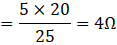
The resistance 5 Ω and 20 Ω are in parallel then the equivalent resistance of 5 Ω and 20 Ω is:
So that the equivalent circuit diagram is:

Step 2:
In the fig.2:
The resistance 6Ω and 4 Ω are in series so the equivalent resistance of 6Ω and 4 Ω is

Now, The resistance 10 Ω and 40 Ω are in parallel, then the equivalent resistance of 10Ω and 40 Ω is:

So that the equivalent circuit diagram is:
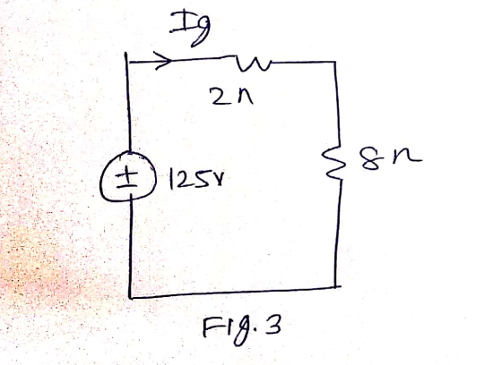
Step 3:
From fig.3, Now the find the current Ig is:
From fig.2, calculate the value of current I1 using the current divider rule:


From fig.1 calculate current IO using the current divider rule:


So that the current Ig and Io are:


Add Answer to:
rrent in tive at the top. 3.28 For the circuit in Fig. P3.28, find i, and...
For the circuit in Fig. P3.31, find i, and then use cur- rent division to find...
 For the circuit in Fig. P3.31, find i, and then use cur- rent division to find i. 3.31 Figure P3.31 8 15 2 2Ω 6 2 20 13 Q
Vs 82 BATZ IOS = eration rrent (ID) for Fig. 3 VD 5V NMOS 10 0 BAT2 R1 1000 IOS . Triode, rrent (In) for Fig...
 Vs 82 BATZ IOS = eration rrent (ID) for Fig. 3 VD 5V NMOS 10 0 BAT2 R1 1000 IOS . Triode, rrent (In) for Fig. 4 Question 4: W a Find the value of Vas b If the threshold voltage of the NMOS = 0.7V, identify the region of operation for the MOSFET (i.e. Triode Saturation or Cutoff) e Write the formula to calculate Current (ID) for the circuit in Figure 3. Fig. 3 Question 5: V=5V ww a...
Draw the dc equivalent circuit and find the Q-point for the amplifier in Fig. Assume Kp...
 Draw the dc equivalent circuit and find the Q-point for the amplifier in Fig. Assume Kp = 400 UA/V2, VTP =-1 V, VDD = 15 V, R1 = 3.3 M2, R2 = 3.3 MO, RD = 24 k1, and R4 = 22 kN. Figure 00W w WM w ΚΩ 7 M R 470k
3.9 Find V, and 1, in the circuit in Fig. P3.9. Va + -- M be...
 3.9 Find V, and 1, in the circuit in Fig. P3.9. Va + -- M be 112 212 3. 30 G 2A 60 60 D4A Figure P3.9
find the voltages V, V, and V, in the circuit of Fig. 1, and the currents...
 find the voltages V, V, and V, in the circuit of Fig. 1, and the currents 1,, l, and I, in the circuit of Fig. 2. + V- R1, 10K2 + R2, 27KV2 1 R3, 10K w - V + Figure 1 W R1, 10K R2, 27K12 R3, 10K<< Figure 2
2.20,2.22,2.29,2.62 6 MA Figure P2.18 2.19 Find 11, and 1, in the network in Fig. P2.19....
 2.20,2.22,2.29,2.62
6 MA Figure P2.18 2.19 Find 11, and 1, in the network in Fig. P2.19. 12 mA 21. Figure P2.19 2.20 Find Vand V. in the circuit in Fig. P2.20. 2v 8 - 2V + Figure P2.20 2.21 Given the circuit diagram in Fig. P2.21, find the following voltages: V V V V V V V V V and V 8 V 12 V Figure P2.16 17 Find Vw in the circuit in Fig. P2.17. 4V- 12v Figure P2.17...
2.20,2.22,2.29,2.62
6 MA Figure P2.18 2.19 Find 11, and 1, in the network in Fig. P2.19. 12 mA 21. Figure P2.19 2.20 Find Vand V. in the circuit in Fig. P2.20. 2v 8 - 2V + Figure P2.20 2.21 Given the circuit diagram in Fig. P2.21, find the following voltages: V V V V V V V V V and V 8 V 12 V Figure P2.16 17 Find Vw in the circuit in Fig. P2.17. 4V- 12v Figure P2.17...
Solve using matrices Use mesh analysis to find vab and io in the circuit of Fig....
 Solve using matrices
Use mesh analysis to find vab and io in the circuit of Fig. 3.89 Figure 3.89: 20Ω 30 52 80 V(+ 20 92 3012 vab 80 V(+ 30 2 20Ω
Solve using matrices
Use mesh analysis to find vab and io in the circuit of Fig. 3.89 Figure 3.89: 20Ω 30 52 80 V(+ 20 92 3012 vab 80 V(+ 30 2 20Ω
Problem 10.14 please 2Ω Figure P10.15 Figure P10.13 10.14 Find I, in the circuit in Fig....
 Problem 10.14 please
2Ω Figure P10.15 Figure P10.13 10.14 Find I, in the circuit in Fig. P10.14. 12Ω 4Ω 4Ω 6/0V Io Figure P10.14
Problem 10.14 please
2Ω Figure P10.15 Figure P10.13 10.14 Find I, in the circuit in Fig. P10.14. 12Ω 4Ω 4Ω 6/0V Io Figure P10.14
Find I, in the circuit of Fig. 2. 4Ω Ι, 22 2Ο | -2Ω j6Ω 60/30°...
 Find I, in the circuit of Fig. 2. 4Ω Ι, 22 2Ο | -2Ω j6Ω 60/30° V (4) ξ8 Ω 3 10 Ω Figure 2
20Ω 30 Ω j20Ω Fig. 1.7 In the circuit of Fig. 1.8, find the RMS phasor...
 20Ω 30 Ω j20Ω Fig. 1.7 In the circuit of Fig. 1.8, find the RMS phasor voltage V so that the 60 Ω resistor absorbs an average power of 240 W. Hence, determine the complex power delivered to each component, the complex power and the power factor delivered by voltage source. Fig. 1.8 2) P1.8
 For the circuit in Fig. P3.31, find i, and then use cur- rent division to find i. 3.31 Figure P3.31 8 15 2 2Ω 6 2 20 13 Q
 Vs 82 BATZ IOS = eration rrent (ID) for Fig. 3 VD 5V NMOS 10 0 BAT2 R1 1000 IOS . Triode, rrent (In) for Fig. 4 Question 4: W a Find the value of Vas b If the threshold voltage of the NMOS = 0.7V, identify the region of operation for the MOSFET (i.e. Triode Saturation or Cutoff) e Write the formula to calculate Current (ID) for the circuit in Figure 3. Fig. 3 Question 5: V=5V ww a...
 Draw the dc equivalent circuit and find the Q-point for the amplifier in Fig. Assume Kp = 400 UA/V2, VTP =-1 V, VDD = 15 V, R1 = 3.3 M2, R2 = 3.3 MO, RD = 24 k1, and R4 = 22 kN. Figure 00W w WM w ΚΩ 7 M R 470k
 3.9 Find V, and 1, in the circuit in Fig. P3.9. Va + -- M be 112 212 3. 30 G 2A 60 60 D4A Figure P3.9
 find the voltages V, V, and V, in the circuit of Fig. 1, and the currents 1,, l, and I, in the circuit of Fig. 2. + V- R1, 10K2 + R2, 27KV2 1 R3, 10K w - V + Figure 1 W R1, 10K R2, 27K12 R3, 10K<< Figure 2
 2.20,2.22,2.29,2.62
6 MA Figure P2.18 2.19 Find 11, and 1, in the network in Fig. P2.19. 12 mA 21. Figure P2.19 2.20 Find Vand V. in the circuit in Fig. P2.20. 2v 8 - 2V + Figure P2.20 2.21 Given the circuit diagram in Fig. P2.21, find the following voltages: V V V V V V V V V and V 8 V 12 V Figure P2.16 17 Find Vw in the circuit in Fig. P2.17. 4V- 12v Figure P2.17...
2.20,2.22,2.29,2.62
6 MA Figure P2.18 2.19 Find 11, and 1, in the network in Fig. P2.19. 12 mA 21. Figure P2.19 2.20 Find Vand V. in the circuit in Fig. P2.20. 2v 8 - 2V + Figure P2.20 2.21 Given the circuit diagram in Fig. P2.21, find the following voltages: V V V V V V V V V and V 8 V 12 V Figure P2.16 17 Find Vw in the circuit in Fig. P2.17. 4V- 12v Figure P2.17...
 Solve using matrices
Use mesh analysis to find vab and io in the circuit of Fig. 3.89 Figure 3.89: 20Ω 30 52 80 V(+ 20 92 3012 vab 80 V(+ 30 2 20Ω
Solve using matrices
Use mesh analysis to find vab and io in the circuit of Fig. 3.89 Figure 3.89: 20Ω 30 52 80 V(+ 20 92 3012 vab 80 V(+ 30 2 20Ω
 Problem 10.14 please
2Ω Figure P10.15 Figure P10.13 10.14 Find I, in the circuit in Fig. P10.14. 12Ω 4Ω 4Ω 6/0V Io Figure P10.14
Problem 10.14 please
2Ω Figure P10.15 Figure P10.13 10.14 Find I, in the circuit in Fig. P10.14. 12Ω 4Ω 4Ω 6/0V Io Figure P10.14
 Find I, in the circuit of Fig. 2. 4Ω Ι, 22 2Ο | -2Ω j6Ω 60/30° V (4) ξ8 Ω 3 10 Ω Figure 2
 20Ω 30 Ω j20Ω Fig. 1.7 In the circuit of Fig. 1.8, find the RMS phasor voltage V so that the 60 Ω resistor absorbs an average power of 240 W. Hence, determine the complex power delivered to each component, the complex power and the power factor delivered by voltage source. Fig. 1.8 2) P1.8
Most questions answered within 3 hours.
-
Based on the range, which of the following sets of scores has
the greatest variability? 3,...
asked 1 hour ago -
Ripples in a pond travel at a velocity of 3 m/s with one peak
passing a...
asked 54 minutes ago -
A man stands on the roof of a building of height 13.0 mm and
throws a...
asked 1 hour ago -
The extent to which assets are financed by borrowed funds and
other liabilities is indicated by:...
asked 2 hours ago -
Explain in detail
Germany is the fifth largest economy
explain what goods and services Germany specializes...
asked 2 hours ago -
The density of platinum is 21.45 g/mL. If a cube of platinum
with a mass of...
asked 2 hours ago -
Accounts Receivable
Sales
A/R Posting
Extended Sales Invoice
Packing Slip
Compare invoice to packing slip 2...
asked 2 hours ago -
Michaella, age 23, is a full-time law student and is claimed by
her parents as a...
asked 2 hours ago -
Why are polymers not typically casted into products?
asked 2 hours ago -
When rolling a die 129 times, what is the probability of rolling
a 6 no more...
asked 2 hours ago -
4. A call option currently sells for $7.75. It has a strike
price of $85 and...
asked 2 hours ago -
1.
You need to prepare 10.0 liters of an acid aqueous solution with a
pH of...
asked 2 hours ago