
Homework Answers


Add Answer to:
Problem 4 = 20A Find i(t) and v(t) for t > 0 in the circuit below...
2. Consider the circuit shown below. The switch in the circuit is closed at t =...
 2. Consider the circuit shown below. The switch in the circuit is closed at t = 0 and at that moment, the inductor is in DC steady state. Fill in the table below. t-0 1Ω 1 A i,(t) 3 V 5Ω 5 Q 1 H
a) Use MultiSim to find Vo in the circuit below. Paste your Multisim circuit showing the value of Vo in the space below...
 a) Use MultiSim to find Vo in the circuit below. Paste your
Multisim circuit showing the value of Vo in the space below.
b) Use mesh analysis to solve the same problem by hand. Show
your work in the space below. Compare the Multisim answer to that
obtained by hand. Are they the same?
5 A 2Ω 20 V 412 40 V (+ V: 27.1 V V(PP): 2.07 pv V(rms): 0Vv V(dc): 27.1V V(freq): 5A R2 R3 PR1 R1 2Ω...
a) Use MultiSim to find Vo in the circuit below. Paste your
Multisim circuit showing the value of Vo in the space below.
b) Use mesh analysis to solve the same problem by hand. Show
your work in the space below. Compare the Multisim answer to that
obtained by hand. Are they the same?
5 A 2Ω 20 V 412 40 V (+ V: 27.1 V V(PP): 2.07 pv V(rms): 0Vv V(dc): 27.1V V(freq): 5A R2 R3 PR1 R1 2Ω...
Solving for The switch in the circuit below has been closed for a long time and it opens at t = 0. Find the following: f...
 Solving for The switch in the
circuit below has been closed for a long time and it opens at t =
0. Find the following:
for b) can you solve it without using Laplace transform? As in
no s domain, thank you
1. The switch in the circuit below has been closed for a long time and it opens at t = 0. Find the following: (a) (20 points) v(0%), and v.(0%) for t < 0. (b) (20 points) v(t),...
Solving for The switch in the
circuit below has been closed for a long time and it opens at t =
0. Find the following:
for b) can you solve it without using Laplace transform? As in
no s domain, thank you
1. The switch in the circuit below has been closed for a long time and it opens at t = 0. Find the following: (a) (20 points) v(0%), and v.(0%) for t < 0. (b) (20 points) v(t),...
Question 1: In the following circuit, find i() for t> 0. Assume that the switch has...
 Question 1: In the following circuit, find i() for t> 0. Assume that the switch has been closed for a long time and is opened at t-0. 6Ω 1.5Ω 0.1 F io) 1.25H
Question 4 Find i(t) for t >0 for the circuit below. 4Ω 12 V 5 H...
 Question 4 Find i(t) for t >0 for the circuit below. 4Ω 12 V 5 H 3 A
Apply Thévenin's theorem twice to find Vo in the circuit in the figure below.
 Apply Thévenin's theorem twice to find Vo in the circuit in the
figure below.
Chapter 8, Problem 8.126 Apply Thévenin's theorem twice to find Vo in the circuit in the figure below. 1Ω 2Ω ΙΩ 20Ω a Find the real part of V (b) Find the imaginary part of vo
Chapter 8, Problem 8.126 Apply Thévenin's theorem twice to find Vo in the circuit in the figure below. 1Ω 2Ω ΙΩ 20Ω a Find the real part of V (b)...
Apply Thévenin's theorem twice to find Vo in the circuit in the
figure below.
Chapter 8, Problem 8.126 Apply Thévenin's theorem twice to find Vo in the circuit in the figure below. 1Ω 2Ω ΙΩ 20Ω a Find the real part of V (b) Find the imaginary part of vo
Chapter 8, Problem 8.126 Apply Thévenin's theorem twice to find Vo in the circuit in the figure below. 1Ω 2Ω ΙΩ 20Ω a Find the real part of V (b)...
Find i(t) for t>0 for the circuit in Fig. 16.37 Assume i(t)- [6(t) + 35(t)]mA 16.14...
 Find i(t) for t>0 for the circuit in Fig. 16.37 Assume i(t)- [6(t) + 35(t)]mA 16.14 1Ω i(t) ist) ( 0.2 H 2Ω
1. Find v(t) fort> 0 in the circuit in below: t=0 222 w 622 w +...
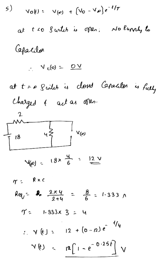
 1. Find v(t) fort> 0 in the circuit in below: t=0 222 w 622 w + 10V 2 F +1 50 V Assume the switch has been open for a long time and is closed at t=0.
Find i(t) in the circuit for t > 0
 Find i(t) in the circuit for t > 0. Assume that the switch has been closed for a very long time, and opened at t = 0.
Circuit 1 Transient response of a series RLC circuit The two switches in the circuit in...
 Circuit 1 Transient response of a series RLC circuit The two switches in the circuit in Figure 8 operate synchronously. When switch 1 is in position "a", switch 2 is closed. When switch 1 is in position "b", switch 2 is open. Switch 1 has been in position "a" for a very long time. At 1-0, it moves instantaneously to position 4Ω t=0 2 8Ω 100mH 150V| 2Ω 60 V Figure 8: Circuit for Tasks 3 and 4 TASK 3...
 2. Consider the circuit shown below. The switch in the circuit is closed at t = 0 and at that moment, the inductor is in DC steady state. Fill in the table below. t-0 1Ω 1 A i,(t) 3 V 5Ω 5 Q 1 H
 a) Use MultiSim to find Vo in the circuit below. Paste your
Multisim circuit showing the value of Vo in the space below.
b) Use mesh analysis to solve the same problem by hand. Show
your work in the space below. Compare the Multisim answer to that
obtained by hand. Are they the same?
5 A 2Ω 20 V 412 40 V (+ V: 27.1 V V(PP): 2.07 pv V(rms): 0Vv V(dc): 27.1V V(freq): 5A R2 R3 PR1 R1 2Ω...
a) Use MultiSim to find Vo in the circuit below. Paste your
Multisim circuit showing the value of Vo in the space below.
b) Use mesh analysis to solve the same problem by hand. Show
your work in the space below. Compare the Multisim answer to that
obtained by hand. Are they the same?
5 A 2Ω 20 V 412 40 V (+ V: 27.1 V V(PP): 2.07 pv V(rms): 0Vv V(dc): 27.1V V(freq): 5A R2 R3 PR1 R1 2Ω...
 Solving for The switch in the
circuit below has been closed for a long time and it opens at t =
0. Find the following:
for b) can you solve it without using Laplace transform? As in
no s domain, thank you
1. The switch in the circuit below has been closed for a long time and it opens at t = 0. Find the following: (a) (20 points) v(0%), and v.(0%) for t < 0. (b) (20 points) v(t),...
Solving for The switch in the
circuit below has been closed for a long time and it opens at t =
0. Find the following:
for b) can you solve it without using Laplace transform? As in
no s domain, thank you
1. The switch in the circuit below has been closed for a long time and it opens at t = 0. Find the following: (a) (20 points) v(0%), and v.(0%) for t < 0. (b) (20 points) v(t),...
 Question 1: In the following circuit, find i() for t> 0. Assume that the switch has been closed for a long time and is opened at t-0. 6Ω 1.5Ω 0.1 F io) 1.25H
 Question 4 Find i(t) for t >0 for the circuit below. 4Ω 12 V 5 H 3 A
 Apply Thévenin's theorem twice to find Vo in the circuit in the
figure below.
Chapter 8, Problem 8.126 Apply Thévenin's theorem twice to find Vo in the circuit in the figure below. 1Ω 2Ω ΙΩ 20Ω a Find the real part of V (b) Find the imaginary part of vo
Chapter 8, Problem 8.126 Apply Thévenin's theorem twice to find Vo in the circuit in the figure below. 1Ω 2Ω ΙΩ 20Ω a Find the real part of V (b)...
Apply Thévenin's theorem twice to find Vo in the circuit in the
figure below.
Chapter 8, Problem 8.126 Apply Thévenin's theorem twice to find Vo in the circuit in the figure below. 1Ω 2Ω ΙΩ 20Ω a Find the real part of V (b) Find the imaginary part of vo
Chapter 8, Problem 8.126 Apply Thévenin's theorem twice to find Vo in the circuit in the figure below. 1Ω 2Ω ΙΩ 20Ω a Find the real part of V (b)...
 Find i(t) for t>0 for the circuit in Fig. 16.37 Assume i(t)- [6(t) + 35(t)]mA 16.14 1Ω i(t) ist) ( 0.2 H 2Ω
 1. Find v(t) fort> 0 in the circuit in below: t=0 222 w 622 w + 10V 2 F +1 50 V Assume the switch has been open for a long time and is closed at t=0.
 Circuit 1 Transient response of a series RLC circuit The two switches in the circuit in Figure 8 operate synchronously. When switch 1 is in position "a", switch 2 is closed. When switch 1 is in position "b", switch 2 is open. Switch 1 has been in position "a" for a very long time. At 1-0, it moves instantaneously to position 4Ω t=0 2 8Ω 100mH 150V| 2Ω 60 V Figure 8: Circuit for Tasks 3 and 4 TASK 3...
Most questions answered within 3 hours.
-
1.8 zyLab training: Basics (Java)
While the zyLab platform can be used without training, a bit...
asked 3 seconds from now -
The figure below shows an electron passing between two charged
metal plates that create an 100...
asked 2 minutes ago -
A) Calculate the final temperature, in degrees Celsius,
if n and V do not change.
A...
asked 5 minutes ago -
Find the 60th percentile of a standard normal
distribution(3 decimal places) on StatCrunch
asked 19 minutes ago -
This week we discuss the properly classified Balance Sheet.
Recall that the value of assets is...
asked 18 minutes ago -
Determine the molar concentration of Cl- ions in a 1.00 M
solution of AgCl2- with no...
asked 24 minutes ago -
You work for a defense company in their characterization
department. Your superior brings you 0.5 g...
asked 33 minutes ago -
An elevator has a placard stating that the maximum capacity is
1600lb—10 passengers. So, 10 adult...
asked 36 minutes ago -
The special causes of variation ________.
A) cannot be identified
B) cannot be eliminated
C) cannot...
asked 50 minutes ago -
PYTHON Hello can someone create the following functions?
I'm not sure how to start on them....
asked 55 minutes ago -
The Final Paper must have as a focus the same topic as your
topic selection assignment...
asked 50 minutes ago -
Calculate the activation energy, Ea, for
N2O5(g) --> 2 NO2(g) + 1/2 O2(g)
given k (at...
asked 46 minutes ago