
Homework Answers
Option - D
Add Answer to:
4) The capacitors in the network shown in the figure all have a capacitance of 5.0...
What is the equivalent capacitance of the capacitor network shown in Fig. 24-7? (All the...
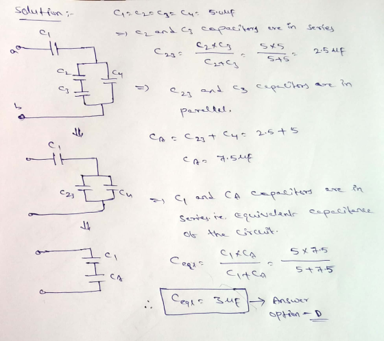
What is the equivalent capacitance of the capacitor network shown in Fig. 24-7? (All the capacitors have a capacitance C = 5 µF. The voltage of the battery is V =6V.)Answera)3 µFb)5 µFc)10 µFd)20 µFe)1 µF
The C1 -2.0 uF and 3.0 uF capacitor equivalent capacitance is X1-5.0 μF. Likewise, the C2-3.0...
 The C1 -2.0 uF and 3.0 uF capacitor equivalent capacitance is X1-5.0 μF. Likewise, the C2-3.0 μF and 6.0 μF capacitors are also in parallel and have an equivalent capacitance of Y1-9.0屹The upper branch in Figure 26.11b now consists of a 4.0 μF capacitor and a 5.0 μF In series, which combine to give x2 according to the following equation. rs are in parallel and combine according to Ceq C1+C2. Their Likewise, the lower branch in Figure 26.11b consists of...
CAPACITANCE In the circuit shown in Figure 1 below the capacitors are connected with an applied...
 CAPACITANCE In the circuit shown in Figure 1 below the capacitors are connected with an applied de potential difference across terminals a-b of V.- 200.0V. The capacitors have values C - 3.0 F, C = 3.0 uF, C, -6.0 pF, and C -6.0 F. Figure 1 Calculate the equivalent capacitance of the circuit. 1(a) ANSWER 1(b) Calculate the potential difference between locations c and don the circuit. ANSWER
Four capacitors are arranged in the circuit shown in the figure. The capacitors have the values...
 Four capacitors are arranged in the circuit shown in the figure. The capacitors have the values G = 22.5 UF, C = 45.5 pF, C; = 50.5 pF, and Cd = 40.5 pF, and the power supply is at voltage V = 23.5 V. What is the equivalent capacitance of the circuit? equivalent capacitance: What is the charge on capacitor C2? charge on C: What is the potential difference across capacitor C;? potential difference across C3: What is the potential...
What is the equivalent capacitance of the capacitor network shown in Fig. 24-7? (All the...
What is the equivalent capacitance of the capacitor network shown in Fig. 24-7? (All the capacitors have a capacitance C = 5 μF. The voltage of the battery isV = 6V.)Answer3 μF5 μF10 μF20 μF1 μF
20 of 22 > Four capacitors are arranged in the circuit shown in the figure. The...
 20 of 22 > Four capacitors are arranged in the circuit shown in the figure. The capacitors have the values C 26.5 uF, C2 45.5 uF, C3 50.5 pF, and C4 40.5 uF, and the power supply is at voltage V 31.5 V C What is the equivalent capacitance of the circuit? C equivalent capacitance: 8.3 V What is the charge capacitor C2? on C. charge C2: 5.75 C on What is the potential difference across capacitor C3? about us...
A Review Constants Part E - Determine the equivalent capacitance across terminals a and b Learning...
 A Review Constants Part E - Determine the equivalent capacitance across terminals a and b Learning Goal: To reduce series-parallel combinations of inductors or capacitors to an equivalent inductance or capacitance. Inductors in series and parallel combine like resistors in series and parallel. It is possible to use Kirchhoff's current law to find the current through the equivalent inductance. Moreover, capacitors in series combine like resistors in parallel and vice versa. It is possible to use Kirchhoff's voltage law to...
9. What is the equivalent capacitance of the combination of the capacitors as shown in figure?...
 9. What is the equivalent capacitance of the combination of the capacitors as shown in figure? 313 o 2.5 H 3.33 4.4 3.1+10-13.13pF 0.30 μF 10. What is the equivalent capacitance of the combination of the capacitors as shown in figure? 0 2.5 uF .1: 343+2S: 5.43p 10 μF 3.33 +
An RC circuit is shown. The equivalent capacitance for the capacitor network is Cac = 12...
 An RC circuit is shown. The equivalent capacitance for the capacitor network is Cac = 12 uF. The equivalent resistance for the resistor network is Rce = 800 12 The capacitors are initially uncharged, and the switch S is closed at t = 0. a) Find C3. [4 points] b) Find R1: [4 points] c) Find the current i(0) in the circuit at t= 0. [4 points] d) Find Vac in the circuit at t = 00. [3 points] e)...
Prob. 2. The figure shows a network of three capacitors, C1 = 3.0uF, C2 = 4.OuF,...
 Prob. 2. The figure shows a network of three capacitors, C1 = 3.0uF, C2 = 4.OuF, and C3 = 8.OuF, connected to a constant applied potential Vac across terminals a and C. The capacitors in the network are fully charged, and the charge on C2 is 60.0°C. the time [b]What is the value (in units of uF) of the equivalent capacitance Cac of the three-capacitor network between points a and c? (Example: If your answer is 12.0uF, enter your answer...
 The C1 -2.0 uF and 3.0 uF capacitor equivalent capacitance is X1-5.0 μF. Likewise, the C2-3.0 μF and 6.0 μF capacitors are also in parallel and have an equivalent capacitance of Y1-9.0屹The upper branch in Figure 26.11b now consists of a 4.0 μF capacitor and a 5.0 μF In series, which combine to give x2 according to the following equation. rs are in parallel and combine according to Ceq C1+C2. Their Likewise, the lower branch in Figure 26.11b consists of...
 CAPACITANCE In the circuit shown in Figure 1 below the capacitors are connected with an applied de potential difference across terminals a-b of V.- 200.0V. The capacitors have values C - 3.0 F, C = 3.0 uF, C, -6.0 pF, and C -6.0 F. Figure 1 Calculate the equivalent capacitance of the circuit. 1(a) ANSWER 1(b) Calculate the potential difference between locations c and don the circuit. ANSWER
 Four capacitors are arranged in the circuit shown in the figure. The capacitors have the values G = 22.5 UF, C = 45.5 pF, C; = 50.5 pF, and Cd = 40.5 pF, and the power supply is at voltage V = 23.5 V. What is the equivalent capacitance of the circuit? equivalent capacitance: What is the charge on capacitor C2? charge on C: What is the potential difference across capacitor C;? potential difference across C3: What is the potential...
 20 of 22 > Four capacitors are arranged in the circuit shown in the figure. The capacitors have the values C 26.5 uF, C2 45.5 uF, C3 50.5 pF, and C4 40.5 uF, and the power supply is at voltage V 31.5 V C What is the equivalent capacitance of the circuit? C equivalent capacitance: 8.3 V What is the charge capacitor C2? on C. charge C2: 5.75 C on What is the potential difference across capacitor C3? about us...
 A Review Constants Part E - Determine the equivalent capacitance across terminals a and b Learning Goal: To reduce series-parallel combinations of inductors or capacitors to an equivalent inductance or capacitance. Inductors in series and parallel combine like resistors in series and parallel. It is possible to use Kirchhoff's current law to find the current through the equivalent inductance. Moreover, capacitors in series combine like resistors in parallel and vice versa. It is possible to use Kirchhoff's voltage law to...
 9. What is the equivalent capacitance of the combination of the capacitors as shown in figure? 313 o 2.5 H 3.33 4.4 3.1+10-13.13pF 0.30 μF 10. What is the equivalent capacitance of the combination of the capacitors as shown in figure? 0 2.5 uF .1: 343+2S: 5.43p 10 μF 3.33 +
 An RC circuit is shown. The equivalent capacitance for the capacitor network is Cac = 12 uF. The equivalent resistance for the resistor network is Rce = 800 12 The capacitors are initially uncharged, and the switch S is closed at t = 0. a) Find C3. [4 points] b) Find R1: [4 points] c) Find the current i(0) in the circuit at t= 0. [4 points] d) Find Vac in the circuit at t = 00. [3 points] e)...
 Prob. 2. The figure shows a network of three capacitors, C1 = 3.0uF, C2 = 4.OuF, and C3 = 8.OuF, connected to a constant applied potential Vac across terminals a and C. The capacitors in the network are fully charged, and the charge on C2 is 60.0°C. the time [b]What is the value (in units of uF) of the equivalent capacitance Cac of the three-capacitor network between points a and c? (Example: If your answer is 12.0uF, enter your answer...
Most questions answered within 3 hours.
-
Do not neglect the old for the new. The existing business must
not lose priority simply...
asked 26 minutes ago -
Kylie is a single mom with two dependent children,
Tanner, age 7 and Olivia, age 11....
asked 1 hour ago -
Phosphorous + bromine = phosphorous tribromide. If 35.0 g of
bromine are reacted and 27.9 grams...
asked 3 hours ago -
Derive the long wavelength limit of the Planck energy density
distribution
asked 3 hours ago -
Calculate the pH of each of the following solutions.
0.50 M HBr
3.1×10⁻⁴ M KOH
4.2×10⁻⁵...
asked 6 hours ago -
For the year ended December 31, Depot Max’s cost of merchandise
sold was $85,600. Inventory at the...
asked 6 hours ago -
Week 10 - Professional Memo Assignment
Professional Memo Assignment
Your mission for this week, should you...
asked 6 hours ago -
Write a Python program that stores the data for each
player on the team, and it...
asked 6 hours ago -
In
the last 3 months, mike never knows when he is going to get his
allowance...
asked 7 hours ago -
Is Ca(OH)2 a Bronsted base, Lewis base, or both? Why?
asked 7 hours ago -
1A- Why don’t voters complain about U.S. tariffs on imported
sugar?
Because sugar is only a...
asked 7 hours ago -
Cash Payback Period
Primera Banco is evaluating two capital investment proposals for
a drive-up ATM kiosk,...
asked 7 hours ago