
Homework Answers

Add Answer to:
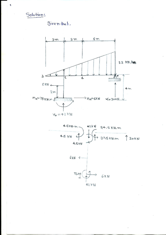
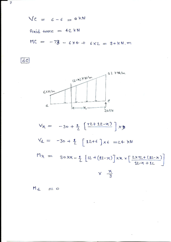
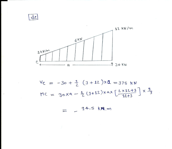
Draw Free Body Diagrams (FBD) for member "be" and "ce" 12 kN/m 6 kN 4 m...
Exercise 6: Draw the free-body diagrams for member ADB and determine the support reactions at A...
 Exercise 6: Draw the free-body diagrams for member ADB and determine the support reactions at A and B. 12' 36 K 6" 12" 65
5. Draw the shear and moment diagrams for each member of the frame 6 kN/m B...
 5. Draw the shear and moment diagrams for each member of the frame 6 kN/m B 1.5 m 12 KN 1.5 m
In the figure below draw the free body diagrams for all three members. 3.) In the figure below draw the free body diagrams for all three members. s) 3 m 2 m 1 m 3 kN 1.5 m 3.) In the figure...
 In the figure below draw the free body
diagrams for all three members.
3.) In the figure below draw the free body diagrams for all three members. s) 3 m 2 m 1 m 3 kN 1.5 m
3.) In the figure below draw the free body diagrams for all three members. s) 3 m 2 m 1 m 3 kN 1.5 m
In the figure below draw the free body
diagrams for all three members.
3.) In the figure below draw the free body diagrams for all three members. s) 3 m 2 m 1 m 3 kN 1.5 m
3.) In the figure below draw the free body diagrams for all three members. s) 3 m 2 m 1 m 3 kN 1.5 m
Draw Shear and Bending Moment diagrams for the following beam. You MUST show free body diagrams...
 Draw Shear and Bending Moment diagrams for the following beam.
You MUST show free body diagrams for each required cut and solve
equations for V and M.
10 kN 3 kN/m
Draw Shear and Bending Moment diagrams for the following beam.
You MUST show free body diagrams for each required cut and solve
equations for V and M.
10 kN 3 kN/m
Only question 3-3, draw a FBD 3-1* to 3-4 Sketch a free-body diagram of each element...
 Only question 3-3, draw a
FBD
3-1* to 3-4 Sketch a free-body diagram of each element in the figure. Compute the magnitude and direction of each force using an algebraic or vector method, as specified. 100 lbf 100 lbf 12 in 10 in 6 in 12 in 10 in 10 in 10 in- Problem 3-1 Problem 3-2 F-400 N 30° F=0.8 KN -0.9 m IE Problem 3-3 Problem 3-4
Only question 3-3, draw a
FBD
3-1* to 3-4 Sketch a free-body diagram of each element in the figure. Compute the magnitude and direction of each force using an algebraic or vector method, as specified. 100 lbf 100 lbf 12 in 10 in 6 in 12 in 10 in 10 in 10 in- Problem 3-1 Problem 3-2 F-400 N 30° F=0.8 KN -0.9 m IE Problem 3-3 Problem 3-4
Test #3 (Chapter 6) Draw all necessary free body diagrams for each problem. The compound beam...
 Test #3 (Chapter 6) Draw all necessary free body diagrams for each problem. The compound beam is fixed at A and supported by rockers at B and C. There are pins at D and E. Determine the support reactions at A, B, and C. 1. 15 kN 30 kN m 6 m 6 m 2 m 2 m 2 m
Problem 05.011- Using a free body diagram, draw V and M diagrams and determine maximum values...
 Problem 05.011- Using a free body diagram, draw V and M diagrams and determine maximum values of V and M Consider the given beam and loading where Pa 4 kN 450 N-m 300 mm 300 mm 200 mm References eBook & Resources Problem 05 ofn Using a free bödy diegram. draw V D ond Mdiagiroms ondi geocimine am volues of Section Break
Draw the free body diagrams for the figures Draw the free body Diagram for the figures...
 Draw the free body diagrams for the figures
Draw the free body Diagram for the figures below. 20 1. 65° 1.7 m 12 m S 250 m
Draw the free body diagrams for the figures
Draw the free body Diagram for the figures below. 20 1. 65° 1.7 m 12 m S 250 m
Id. [9 points] Draw a free-body of member AC. 20° 800 lb le. For the figure...
 Id. [9 points] Draw a free-body of member AC. 20° 800 lb le. For the figure below, draw the following free-body diagrams. All contact surfaces are frictionless. Be sure that you complete the free-body diagrams properly so that you could solve for the unknowns using the set of three diagrams that you create (but do not solve for anything; I just want diagrams) 3 ft 3 ft [9 points] Draw a free-body of member AC. [9 points] Draw a free-body...
For the two frames given below Compute the Support Reactions Draw the Free Body Diagrams for...
 For the two frames given below Compute the Support Reactions Draw the Free Body Diagrams for all members, and joints with concentrated load or moment Draw the Bending Moment Diagram, Shear Force Diagram, and Axial Force Diagram using the sign conventions and labeling scheme taught in the class Draw the Qualitative Deflected Shape, clearly showing the Inflection Points, if any. 1. (50 points) 45 k Need FBD 3 k/ft 15 ft 2. (50 points) 15 kN/m F G 65 kN...
 Exercise 6: Draw the free-body diagrams for member ADB and determine the support reactions at A and B. 12' 36 K 6" 12" 65
 5. Draw the shear and moment diagrams for each member of the frame 6 kN/m B 1.5 m 12 KN 1.5 m
 In the figure below draw the free body
diagrams for all three members.
3.) In the figure below draw the free body diagrams for all three members. s) 3 m 2 m 1 m 3 kN 1.5 m
3.) In the figure below draw the free body diagrams for all three members. s) 3 m 2 m 1 m 3 kN 1.5 m
In the figure below draw the free body
diagrams for all three members.
3.) In the figure below draw the free body diagrams for all three members. s) 3 m 2 m 1 m 3 kN 1.5 m
3.) In the figure below draw the free body diagrams for all three members. s) 3 m 2 m 1 m 3 kN 1.5 m
 Draw Shear and Bending Moment diagrams for the following beam.
You MUST show free body diagrams for each required cut and solve
equations for V and M.
10 kN 3 kN/m
Draw Shear and Bending Moment diagrams for the following beam.
You MUST show free body diagrams for each required cut and solve
equations for V and M.
10 kN 3 kN/m
 Only question 3-3, draw a
FBD
3-1* to 3-4 Sketch a free-body diagram of each element in the figure. Compute the magnitude and direction of each force using an algebraic or vector method, as specified. 100 lbf 100 lbf 12 in 10 in 6 in 12 in 10 in 10 in 10 in- Problem 3-1 Problem 3-2 F-400 N 30° F=0.8 KN -0.9 m IE Problem 3-3 Problem 3-4
Only question 3-3, draw a
FBD
3-1* to 3-4 Sketch a free-body diagram of each element in the figure. Compute the magnitude and direction of each force using an algebraic or vector method, as specified. 100 lbf 100 lbf 12 in 10 in 6 in 12 in 10 in 10 in 10 in- Problem 3-1 Problem 3-2 F-400 N 30° F=0.8 KN -0.9 m IE Problem 3-3 Problem 3-4
 Test #3 (Chapter 6) Draw all necessary free body diagrams for each problem. The compound beam is fixed at A and supported by rockers at B and C. There are pins at D and E. Determine the support reactions at A, B, and C. 1. 15 kN 30 kN m 6 m 6 m 2 m 2 m 2 m
 Problem 05.011- Using a free body diagram, draw V and M diagrams and determine maximum values of V and M Consider the given beam and loading where Pa 4 kN 450 N-m 300 mm 300 mm 200 mm References eBook & Resources Problem 05 ofn Using a free bödy diegram. draw V D ond Mdiagiroms ondi geocimine am volues of Section Break
 Draw the free body diagrams for the figures
Draw the free body Diagram for the figures below. 20 1. 65° 1.7 m 12 m S 250 m
Draw the free body diagrams for the figures
Draw the free body Diagram for the figures below. 20 1. 65° 1.7 m 12 m S 250 m
 Id. [9 points] Draw a free-body of member AC. 20° 800 lb le. For the figure below, draw the following free-body diagrams. All contact surfaces are frictionless. Be sure that you complete the free-body diagrams properly so that you could solve for the unknowns using the set of three diagrams that you create (but do not solve for anything; I just want diagrams) 3 ft 3 ft [9 points] Draw a free-body of member AC. [9 points] Draw a free-body...
 For the two frames given below Compute the Support Reactions Draw the Free Body Diagrams for all members, and joints with concentrated load or moment Draw the Bending Moment Diagram, Shear Force Diagram, and Axial Force Diagram using the sign conventions and labeling scheme taught in the class Draw the Qualitative Deflected Shape, clearly showing the Inflection Points, if any. 1. (50 points) 45 k Need FBD 3 k/ft 15 ft 2. (50 points) 15 kN/m F G 65 kN...
Most questions answered within 3 hours.
-
Why is QE a controversial monetary policy tool.
A. It may lead to excessive inflation.B. By...
asked 1 hour ago -
Principles of Programming midterm study guide help!
1.)
______ Which of the following would reference the...
asked 32 minutes ago -
Romeo wishes to throw a bouquet of flowers to Juliet, who is on
a second-story balcony,...
asked 46 minutes ago -
A finite potential well has depth U0 = 2.78 eV . What is the
penetration distance...
asked 1 hour ago -
1. The bus bars of a power station are in two sections A and B
separated...
asked 1 hour ago -
Fiscal policy is the deliberate manipulation of taxes and
government spending to alter GDP, employment, inflation...
asked 2 hours ago -
evaluating an expression using only one digit and + and - as
operators ....3+5-1+7-5+8
-----------------------
stack...
asked 2 hours ago -
Two concentric current loops lie in the same plane. The smaller
loop has a radius of...
asked 2 hours ago -
1)Which of the following is an
important difference between qualified and nonqualified retirement
plans?
a. Qualified...
asked 3 hours ago -
What's the streaming business's problem on the
horizon?
asked 3 hours ago -
I need help with writing the conclusion for this online lab
report
Abstract
By testing the...
asked 4 hours ago -
For the reaction 1N2+3H2-----> 2NH3, would the reaction rate
trend be: delta[NH3]/ delta t = -2...
asked 4 hours ago