
Homework Answers

Add Answer to:
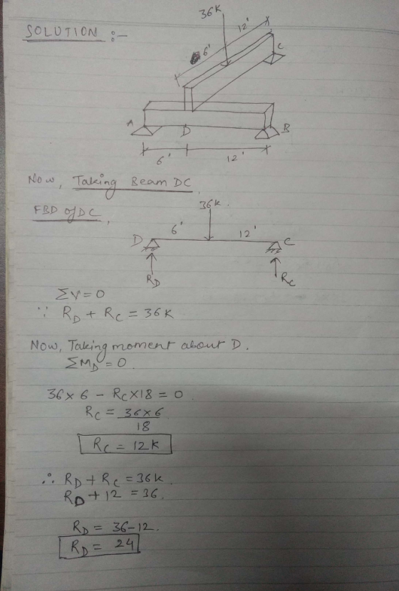
Exercise 6: Draw the free-body diagrams for member ADB and determine the support reactions at A...
Draw free body diagrams and determine all support reactions (magnitude, units, and direction) and force in...
 Draw free body diagrams and determine all support reactions (magnitude, units, and direction) and force in cable CB. For RISA-2D, consider the cable as a member but release both ends. 2 k/ft8 kips 10 ft 6 ft 4 ft
For the two frames given below Compute the Support Reactions Draw the Free Body Diagrams for...
 For the two frames given below Compute the Support Reactions Draw the Free Body Diagrams for all members, and joints with concentrated load or moment Draw the Bending Moment Diagram, Shear Force Diagram, and Axial Force Diagram using the sign conventions and labeling scheme taught in the class Draw the Qualitative Deflected Shape, clearly showing the Inflection Points, if any. 1. (50 points) 45 k Need FBD 3 k/ft 15 ft 2. (50 points) 15 kN/m F G 65 kN...
3. For the frame shown in Fig. 3, (a) (7%) determine the support reactions, (b) (6%) draw the fre...
 3. For the frame shown in Fig. 3, (a) (7%) determine the support reactions, (b) (6%) draw the free-body diagrams of member AB and member CBD; (c) (12%) replace the loading on the frame by a single resultant force, and specify where its line of action intersects member CD, measured from end C 150 N 500 N 3 m 3m 2 m 400 N -m 0.35 m 0.35 m 3 m 500 N 35° Fig. 3 Fig. 2 Fig. 1...
Draw the free body diagrams for the figures Draw the free body Diagram for the figures...
 Draw the free body diagrams for the figures
Draw the free body Diagram for the figures below. 20 1. 65° 1.7 m 12 m S 250 m
Draw the free body diagrams for the figures
Draw the free body Diagram for the figures below. 20 1. 65° 1.7 m 12 m S 250 m
Draw Free Body Diagrams (FBD) for member "be" and "ce" 12 kN/m 6 kN 4 m...
 Draw Free Body Diagrams (FBD) for member "be" and "ce" 12 kN/m 6 kN 4 m V. -30 kN H6 kN M 78 kN -m v,-42 kN
2. (a) Draw a free body diagram for member ABC shown below. (b) Determine the reactions...
 2. (a) Draw a free body diagram for member ABC shown below. (b) Determine the reactions at the supports A and C. P = 10 kN and a = 1 m. Begin your solution on this page 30
Draw the free-body diagram of the member ABC, which is supported by a pin at A...
 Draw the free-body diagram of the member ABC, which is supported by a pin at A and a horizontal short link BD. Neglect the weight of ABC and determine support reactions at A and B. 0.5 m 30° 50 kg
Test #3 (Chapter 6) Draw all necessary free body diagrams for each problem. The compound beam...
 Test #3 (Chapter 6) Draw all necessary free body diagrams for each problem. The compound beam is fixed at A and supported by rockers at B and C. There are pins at D and E. Determine the support reactions at A, B, and C. 1. 15 kN 30 kN m 6 m 6 m 2 m 2 m 2 m
GET THE FORCES IN EACH MEMBER BY GETTING REACTIONS AND DOING FREE BODY DIAGRAMS AT EACH...
 GET THE FORCES IN EACH MEMBER BY GETTING REACTIONS AND DOING
FREE BODY DIAGRAMS AT EACH POINT, STATE IF THE MEMBER IS IN
COMPRESSION OR TENSION. THE DASHED LINES ARE ALSO MEMBERS THEY ARE
USUALLY COMPRESSION MEMBERS BUT I MAY BE WRONG ANALYZE FREELY.
GET THE FORCES IN EACH MEMBER BY GETTING REACTIONS AND DOING
FREE BODY DIAGRAMS AT EACH POINT, STATE IF THE MEMBER IS IN
COMPRESSION OR TENSION. THE DASHED LINES ARE ALSO MEMBERS THEY ARE
USUALLY COMPRESSION MEMBERS BUT I MAY BE WRONG ANALYZE FREELY.
ee-00dy dlagram 4. 125 points] Draw appropriate free-body diagrams to support your analysis. A distributed load...
 ee-00dy dlagram 4. 125 points] Draw appropriate free-body diagrams to support your analysis. A distributed load is applied to horizontal member AB. (a) Determine the magnitude of the force at pin A (b) Determine the magnitude of the force at pin B (c), Determine the magnitude of the force at pin C 4 kN/m 1.5 m1.5 m 3 m Ep> 3 m
 Draw free body diagrams and determine all support reactions (magnitude, units, and direction) and force in cable CB. For RISA-2D, consider the cable as a member but release both ends. 2 k/ft8 kips 10 ft 6 ft 4 ft
 For the two frames given below Compute the Support Reactions Draw the Free Body Diagrams for all members, and joints with concentrated load or moment Draw the Bending Moment Diagram, Shear Force Diagram, and Axial Force Diagram using the sign conventions and labeling scheme taught in the class Draw the Qualitative Deflected Shape, clearly showing the Inflection Points, if any. 1. (50 points) 45 k Need FBD 3 k/ft 15 ft 2. (50 points) 15 kN/m F G 65 kN...
 3. For the frame shown in Fig. 3, (a) (7%) determine the support reactions, (b) (6%) draw the free-body diagrams of member AB and member CBD; (c) (12%) replace the loading on the frame by a single resultant force, and specify where its line of action intersects member CD, measured from end C 150 N 500 N 3 m 3m 2 m 400 N -m 0.35 m 0.35 m 3 m 500 N 35° Fig. 3 Fig. 2 Fig. 1...
 Draw the free body diagrams for the figures
Draw the free body Diagram for the figures below. 20 1. 65° 1.7 m 12 m S 250 m
Draw the free body diagrams for the figures
Draw the free body Diagram for the figures below. 20 1. 65° 1.7 m 12 m S 250 m
 Draw Free Body Diagrams (FBD) for member "be" and "ce" 12 kN/m 6 kN 4 m V. -30 kN H6 kN M 78 kN -m v,-42 kN
 2. (a) Draw a free body diagram for member ABC shown below. (b) Determine the reactions at the supports A and C. P = 10 kN and a = 1 m. Begin your solution on this page 30
 Draw the free-body diagram of the member ABC, which is supported by a pin at A and a horizontal short link BD. Neglect the weight of ABC and determine support reactions at A and B. 0.5 m 30° 50 kg
 Test #3 (Chapter 6) Draw all necessary free body diagrams for each problem. The compound beam is fixed at A and supported by rockers at B and C. There are pins at D and E. Determine the support reactions at A, B, and C. 1. 15 kN 30 kN m 6 m 6 m 2 m 2 m 2 m
 GET THE FORCES IN EACH MEMBER BY GETTING REACTIONS AND DOING
FREE BODY DIAGRAMS AT EACH POINT, STATE IF THE MEMBER IS IN
COMPRESSION OR TENSION. THE DASHED LINES ARE ALSO MEMBERS THEY ARE
USUALLY COMPRESSION MEMBERS BUT I MAY BE WRONG ANALYZE FREELY.
GET THE FORCES IN EACH MEMBER BY GETTING REACTIONS AND DOING
FREE BODY DIAGRAMS AT EACH POINT, STATE IF THE MEMBER IS IN
COMPRESSION OR TENSION. THE DASHED LINES ARE ALSO MEMBERS THEY ARE
USUALLY COMPRESSION MEMBERS BUT I MAY BE WRONG ANALYZE FREELY.
 ee-00dy dlagram 4. 125 points] Draw appropriate free-body diagrams to support your analysis. A distributed load is applied to horizontal member AB. (a) Determine the magnitude of the force at pin A (b) Determine the magnitude of the force at pin B (c), Determine the magnitude of the force at pin C 4 kN/m 1.5 m1.5 m 3 m Ep> 3 m
Most questions answered within 3 hours.
-
What will the standard deviation of these exam grades be? A
square bracket means inclusive, so...
asked 2 minutes ago -
Beginning Retained Earnings are $ 79 comma 000 $79,000; sales
are $ 31 comma 700 $31,700;...
asked 5 minutes ago -
Please explain/demonstrate how to use NLTK to test unigram,
bigram, and trigram character models on guessing...
asked 11 minutes ago -
what you feel is most important to you and why regarding your
typing skills?
asked 12 minutes ago -
Consider a play of the casino game `Quick Draw'. In this game, a
player pays $11...
asked 21 minutes ago -
How do the mechanical features of bone affect its roles as
repositories of phosphate and calcium,...
asked 25 minutes ago -
P agreed to buy 100 barrels of widget oil, which was stored in a
large tank...
asked 26 minutes ago -
The unstable isotope 40K is used for dating rock samples. Its
half-life is 1.28×10⁹y. How many...
asked 28 minutes ago -
Compare and contrast constructed-response items and
selected-response items.
Identify at least one (1) advantage and one...
asked 30 minutes ago -
A) Find the moment of inertia of a 2 meter long stick with a
mass of...
asked 29 minutes ago -
For the code below write a public static main() method
in class Student that:
- creates...
asked 31 minutes ago -
Please show all steps. Thank you
A 1.0-cm-diameter pipe widens to 2.0 cm, then narrows to...
asked 44 minutes ago