![ee-00dy dlagram 4. 125 points] Draw appropriate free-body diagrams to support your analysis. A distributed load is applied to](http://img.homeworklib.com/questions/801ce4c0-f2ef-11eb-a5f8-bf809cfda740.png?x-oss-process=image/resize,w_560)
Homework Answers
Comment below in case of any trouble with the answers. I will try to respond asap.

Add Answer to:
ee-00dy dlagram 4. 125 points] Draw appropriate free-body diagrams to support your analysis. A distributed load...
Reactions of all pins and members must be calculated. Draw the free-body diagram of each member...
 Reactions of all pins and members must be calculated.
Draw the free-body diagram of each member (AB, BC, AD, EDC) and pin (A, B, C, D, E). Then, find all the forces previously reported. Force at C (5 kN) is applied on the pin C 5 kN/m 1 kN/m 1 kN/m 2 kN-m 2 m 1.5 m 1.5 m 5 kN
Reactions of all pins and members must be calculated.
Draw the free-body diagram of each member (AB, BC, AD, EDC) and pin (A, B, C, D, E). Then, find all the forces previously reported. Force at C (5 kN) is applied on the pin C 5 kN/m 1 kN/m 1 kN/m 2 kN-m 2 m 1.5 m 1.5 m 5 kN
Draw free body diagrams and determine all support reactions (magnitude, units, and direction) and force in...
 Draw free body diagrams and determine all support reactions (magnitude, units, and direction) and force in cable CB. For RISA-2D, consider the cable as a member but release both ends. 2 k/ft8 kips 10 ft 6 ft 4 ft
For the two frames given below Compute the Support Reactions Draw the Free Body Diagrams for...
 For the two frames given below Compute the Support Reactions Draw the Free Body Diagrams for all members, and joints with concentrated load or moment Draw the Bending Moment Diagram, Shear Force Diagram, and Axial Force Diagram using the sign conventions and labeling scheme taught in the class Draw the Qualitative Deflected Shape, clearly showing the Inflection Points, if any. 1. (50 points) 45 k Need FBD 3 k/ft 15 ft 2. (50 points) 15 kN/m F G 65 kN...
Fx Fx Fy W EX OD Slot Ах Вх The given frame is subject to a...
 Fx Fx Fy W EX OD Slot Ах Вх The given frame is subject to a distributed load w = 55 kN/m and a horizontal force P = 20 kN. The free body diagrams for members AF and BF are also given. Assume L = 12 m, a = 10 m, b = 10 m, c = 14 m, and d = 2 m for your calculations. Determine reactions at supports A and B and the forces at pin F....
Draw Free Body Diagrams (FBD) for member "be" and "ce" 12 kN/m 6 kN 4 m...
 Draw Free Body Diagrams (FBD) for member "be" and "ce" 12 kN/m 6 kN 4 m V. -30 kN H6 kN M 78 kN -m v,-42 kN
Problem 4: The frame with cross-section given supports the distributed load as shown. Answer the following:...
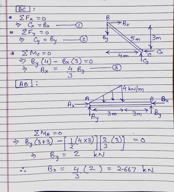
 Problem 4: The frame with cross-section given supports the distributed load as shown. Answer the following: A. Support reactions at A and the force in member BC B. Find the Shear and moment equations for AD section [V(x) and M(x)] and plot the shear and moment diagrams. C. State of stress at D D. State of stress at E 4 kN/m D 20 mm 60 mm 20 mm BA E 5 m 50 mm |-1.5 m -1.5 m --- 3...
Q1. Two rigid members (BCDE and EKN) are connected by a pin at E. The structure is supported by a...
 Q1. Two rigid members (BCDE and EKN) are connected by a pin at E. The structure is supported by a pin at B and two rollers at D and N. An inclined distributed load is acting between E and K with the horizontal (12 kN/m) and vertical (16 kN/m) components. Neglect own weights and thicknesses of the members. f w 26.667 kN/m, 1.5m Draw necessary free body diagrams and determine the reaction forces at roller supports (D and N) and...
please help solve for what is asked in orobkems A-H and the free body diagrams as...
 please help solve for what is asked in orobkems A-H and the
free body diagrams as well. Will upvote if correct
A
B
C
D
E
F
G
H
B 4 m 6 m 3 m 12 m 2 m F=80 N Determine the projected component of the force acting along the axis AB of the pipe. 60° A The 30kg pipe is supported at A by a system of five cords. Determine the force in each cord for equilibrium....
please help solve for what is asked in orobkems A-H and the
free body diagrams as well. Will upvote if correct
A
B
C
D
E
F
G
H
B 4 m 6 m 3 m 12 m 2 m F=80 N Determine the projected component of the force acting along the axis AB of the pipe. 60° A The 30kg pipe is supported at A by a system of five cords. Determine the force in each cord for equilibrium....
A loaded beam with a pin support at B and a rller support at C is shown in Figure 1. The applied loads on the bea...
 A loaded beam with a pin support at B and a rller support at C is shown in Figure 1. The applied loads on the beam are: an anti-clockwise point moment at A, a variably distributed load between B and C, and a clockwise point moment at D g kN/m f kNm h kN m A C 4 m 2 m 2 m Figure 1 The magnitude of the anti-clockwise point moment f in units of kN'm can be found...
Problem 1: (30 points) Draw the shear force (V) and bending moment (M) diagrams for the...
 Problem 1: (30 points) Draw the shear force (V) and bending moment (M) diagrams for the beam AF given below. (B is a pin support, E is a roller support) Find the support reactions first. You are required to show the magnitude and location of all significant points. You don't have to find the equations defining the shear and moment diagrams unless necessary. However, indicate the order of all curves (e.g. 1" degree, 2nd degree, 3od degree). Ignore the depth...
 Reactions of all pins and members must be calculated.
Draw the free-body diagram of each member (AB, BC, AD, EDC) and pin (A, B, C, D, E). Then, find all the forces previously reported. Force at C (5 kN) is applied on the pin C 5 kN/m 1 kN/m 1 kN/m 2 kN-m 2 m 1.5 m 1.5 m 5 kN
Reactions of all pins and members must be calculated.
Draw the free-body diagram of each member (AB, BC, AD, EDC) and pin (A, B, C, D, E). Then, find all the forces previously reported. Force at C (5 kN) is applied on the pin C 5 kN/m 1 kN/m 1 kN/m 2 kN-m 2 m 1.5 m 1.5 m 5 kN
 Draw free body diagrams and determine all support reactions (magnitude, units, and direction) and force in cable CB. For RISA-2D, consider the cable as a member but release both ends. 2 k/ft8 kips 10 ft 6 ft 4 ft
 For the two frames given below Compute the Support Reactions Draw the Free Body Diagrams for all members, and joints with concentrated load or moment Draw the Bending Moment Diagram, Shear Force Diagram, and Axial Force Diagram using the sign conventions and labeling scheme taught in the class Draw the Qualitative Deflected Shape, clearly showing the Inflection Points, if any. 1. (50 points) 45 k Need FBD 3 k/ft 15 ft 2. (50 points) 15 kN/m F G 65 kN...
 Fx Fx Fy W EX OD Slot Ах Вх The given frame is subject to a distributed load w = 55 kN/m and a horizontal force P = 20 kN. The free body diagrams for members AF and BF are also given. Assume L = 12 m, a = 10 m, b = 10 m, c = 14 m, and d = 2 m for your calculations. Determine reactions at supports A and B and the forces at pin F....
 Draw Free Body Diagrams (FBD) for member "be" and "ce" 12 kN/m 6 kN 4 m V. -30 kN H6 kN M 78 kN -m v,-42 kN
 Problem 4: The frame with cross-section given supports the distributed load as shown. Answer the following: A. Support reactions at A and the force in member BC B. Find the Shear and moment equations for AD section [V(x) and M(x)] and plot the shear and moment diagrams. C. State of stress at D D. State of stress at E 4 kN/m D 20 mm 60 mm 20 mm BA E 5 m 50 mm |-1.5 m -1.5 m --- 3...
 Q1. Two rigid members (BCDE and EKN) are connected by a pin at E. The structure is supported by a pin at B and two rollers at D and N. An inclined distributed load is acting between E and K with the horizontal (12 kN/m) and vertical (16 kN/m) components. Neglect own weights and thicknesses of the members. f w 26.667 kN/m, 1.5m Draw necessary free body diagrams and determine the reaction forces at roller supports (D and N) and...
 please help solve for what is asked in orobkems A-H and the
free body diagrams as well. Will upvote if correct
A
B
C
D
E
F
G
H
B 4 m 6 m 3 m 12 m 2 m F=80 N Determine the projected component of the force acting along the axis AB of the pipe. 60° A The 30kg pipe is supported at A by a system of five cords. Determine the force in each cord for equilibrium....
please help solve for what is asked in orobkems A-H and the
free body diagrams as well. Will upvote if correct
A
B
C
D
E
F
G
H
B 4 m 6 m 3 m 12 m 2 m F=80 N Determine the projected component of the force acting along the axis AB of the pipe. 60° A The 30kg pipe is supported at A by a system of five cords. Determine the force in each cord for equilibrium....
 A loaded beam with a pin support at B and a rller support at C is shown in Figure 1. The applied loads on the beam are: an anti-clockwise point moment at A, a variably distributed load between B and C, and a clockwise point moment at D g kN/m f kNm h kN m A C 4 m 2 m 2 m Figure 1 The magnitude of the anti-clockwise point moment f in units of kN'm can be found...
 Problem 1: (30 points) Draw the shear force (V) and bending moment (M) diagrams for the beam AF given below. (B is a pin support, E is a roller support) Find the support reactions first. You are required to show the magnitude and location of all significant points. You don't have to find the equations defining the shear and moment diagrams unless necessary. However, indicate the order of all curves (e.g. 1" degree, 2nd degree, 3od degree). Ignore the depth...
Most questions answered within 3 hours.
-
1. Which of the following is false about photosynthesis?
A. ATP is the molecule used to...
asked 16 minutes ago -
A simple random sample of size n=64 is obtained from a
population with a mean of...
asked 1 hour ago -
(2 dimensions, 1 object, 2 accelerations)
1) A projectile is thrown with a wind. The wind...
asked 2 hours ago -
Brian makes $34,100 per year. How much can Brian expect to
contribute to FICA taxes in...
asked 2 hours ago -
To buy a new house you must borrow $155,000. To do this you take
out a...
asked 3 hours ago -
Spacely Sprockets is evaluating the construction of a new plant
on land the company purchased for...
asked 3 hours ago -
1. Consider a linear regression model of y on K regressors and
an intercept.
(i) Describe...
asked 3 hours ago -
Enter a balanced equation for the reaction between hydrochloric
acid and sodium sulfite.
Express your answer...
asked 4 hours ago -
Give a regular expression describing the language
{x | x ∈ Σ* and x does not...
asked 4 hours ago -
Masses of 1.0 kg, 2.0 kg, and 3.0 kg are each separately subject
to a net...
asked 4 hours ago -
The mode of philosophical argumentation and thought. How do
philosophers think and write? What is important...
asked 4 hours ago -
At the beginning of the unit, you were asked whether you thought
it was appropriate or...
asked 4 hours ago