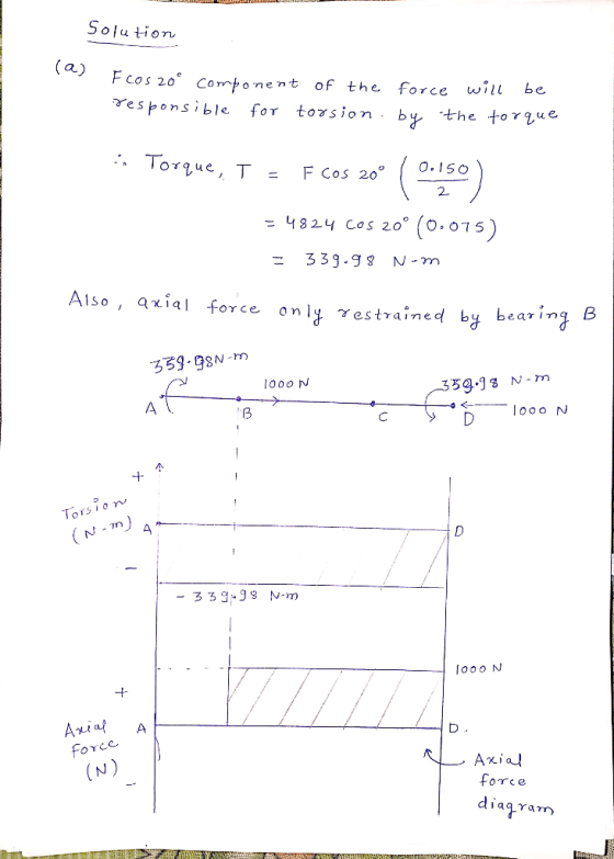
A shaft with a diameter of 43 mm, is shown below On the right hand side at location D a wheel has a force F of 4824N applied. The diameter of this wheel is 150 mm. The torque produced by F is transmitted through the entire shaft to location A where the torque is reacted. There are no other constraints at location A. Bearings, are located at B and C, and provide radial constraint. The bearing at B also provides axial constraint to the shaft. An axial force of 1000 N is applied at the center of the wheel at D. It is in the direction of location A.
a. Create a torsion and axial force diagram for the shaft.
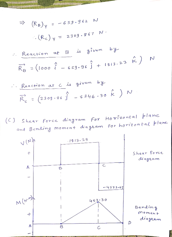
b.Find the reactions at B and C.
c. Create a shear force, V, and bending moment, M diagram for the shaft.
d. Consider where the highest state of stress might occur, both in terms of distance along the beam and where on the cross-section.
e. Draw a stress element at the highest point of stress and find the value of the stresses that act onthe stress element.
f. What are the principle stresses at this point?
g. If the material is AISI 4140 steel and has a yield strength
of 655 MPa, what is the factor of safety  according to the MNST, and
MSST theories?
according to the MNST, and
MSST theories?
Homework Answers


Add Answer to:
A shaft with a diameter of 43 mm, is shown below On the right
hand side...
Problem 1: A shaft, with a diameter of 43 mm, is shown below. On the right-hand side at location ...
 Problem 1: A shaft, with a diameter of 43 mm, is shown below. On the right-hand side at location D a wheel has a force F of 4824N applied. The diameter of this wheel is 150 mm. The torque produced by F is transmitted through the entire shaft to location A where the torque is reacted. There are no other constraints at location A. Bearings, are located at B and C, and provide radial constraint. The bearing at B also...
. A 25-mm diameter steel shaft is loaded by a 1000 N force as shown. Determine (a) the free body diagram of the shaft and reaction loading at the support, (b) the stresses at A (top surface) and d...
 . A 25-mm diameter steel shaft is loaded by a 1000 N force as shown. Determine (a) the free body diagram of the shaft and reaction loading at the support, (b) the stresses at A (top surface) and draw the stress element at A, and (c) the stresses at B (side surface) and draw the stress element at B. 200 mm 100 1000 N
. A 25-mm diameter steel shaft is loaded by a 1000 N force as shown. Determine...
. A 25-mm diameter steel shaft is loaded by a 1000 N force as shown. Determine (a) the free body diagram of the shaft and reaction loading at the support, (b) the stresses at A (top surface) and draw the stress element at A, and (c) the stresses at B (side surface) and draw the stress element at B. 200 mm 100 1000 N
. A 25-mm diameter steel shaft is loaded by a 1000 N force as shown. Determine...
The shaft in the figure below is supported on journal bearings that do not offer any resistance t...
 The shaft in the figure below is supported on journal bearings that do not offer any resistance to axial load. The yield strength of the material is Ơ,-300 MPa and the safety factor is FS-2.5 1) 2) 3) 4) Determine the reaction at the supports. Draw the shear force, bending and torsion moment diagrams Derive an expression for the components of the stress tensor at a cross section of the shaft Neglect the shear stress due to the transverse shear...
The figure shows a transmission shaft. The steel solid shaft is 200 mm long between self-aligning...
 The figure shows a transmission shaft. The steel solid shaft is 200 mm long between self-aligning bearings at A and B. Belt forces in the same horizontal direction) are applied to a 120-mm diameter sheave at C. The left end of the shaft is connected to an electric motor attached to a clutch by means of a flexible coupling. Nothing is attached to the right end (it is free). Assuming the shaft has a constant diameter, d. (a) Perform the...
The figure shows a transmission shaft. The steel solid shaft is 200 mm long between self-aligning...
 The figure shows a transmission shaft. The steel solid shaft is 200 mm long between self-aligning bearings at A and B. Belt forces (in the same horizontal direction) are applied to a 120-mm diameter sheave at C. The left end of the shaft is connected to an electric motor attached to a clutch by means of a flexible coupling. Nothing is attached to the right end (it is free). Assuming the shaft has a constant diameter, d, (a) Perform the...
A 31-mm-diameter solid shaft is subjected to both a torque of T and show them on...
 A 31-mm-diameter solid shaft is subjected to both a torque of T and show them on a stress element. 110 N m and an axial tension load of P 23 N as shown Determine the norma t and shear stresses at 2 Answers: MPa MPa ay MPa
Pulley Diameter = 800 mm Base Plate Diameter = 1200 mm Shaft Mounted Wheel Axial force...
 Pulley Diameter = 800 mm Base Plate Diameter = 1200 mm Shaft Mounted Wheel Axial force F2 along the shaft axis Belt connected to motor with tension force F Figure 1. Side View Belt Bearing A. Bearing B FR = 2 kN --- - - - - - - - - - - > ---- 500 mm 500 mm 500 mm F1 = 500 N 'Fw = 1 kN Figure 2. The design of a fatigue test machine for car...
Question 1 Time Allowed: 2 hours The figure shows a transmission shaft. The steel solid shaft...
 Question 1 Time Allowed: 2 hours The figure shows a transmission shaft. The steel solid shaft is 200 mm long between self-aligning bearings at A and B. Belt forces (in the same horizontal direction) are applied to a 120-mm diameter sheave at C. The left end of the shaft is connected to an electric motor attached to a clutch by means of a flexible coupling. Nothing is attach to the right end (it is free). Assuming the shaft has a...
2) Two forces P- 18 kN and F 15 kN are applied to the shaft with a diameter of D - 40 mm, as shown. A torque T= 750 N·m is also applied on the free end of the shaft. Determine the location and magnit...
 2) Two forces P- 18 kN and F 15 kN are applied to the shaft with a diameter of D - 40 mm, as shown. A torque T= 750 N·m is also applied on the free end of the shaft. Determine the location and magnitudes of maximum normal and shear stresses developed in the shaft. For full credit, show your work (40 points). T IP
2) Two forces P- 18 kN and F 15 kN are applied to the shaft...
2) Two forces P- 18 kN and F 15 kN are applied to the shaft with a diameter of D - 40 mm, as shown. A torque T= 750 N·m is also applied on the free end of the shaft. Determine the location and magnitudes of maximum normal and shear stresses developed in the shaft. For full credit, show your work (40 points). T IP
2) Two forces P- 18 kN and F 15 kN are applied to the shaft...
A cantilevered cylindrical shaft of length 1.6m and diameter 100 mm is loaded by the force...
 A cantilevered cylindrical shaft of length 1.6m and diameter 100 mm is loaded by the force vector F = -3; -5j + 10k kN applied 20 mm above the cross-sectional centroid on the end of the shaft, as shown. Note that the drawing does not correctly indicate the direction of the vector F (the direction of the vector F is given by the vector expression above), but it does correctly indicate the location that the vector is applied. 800 mm...
 Problem 1: A shaft, with a diameter of 43 mm, is shown below. On the right-hand side at location D a wheel has a force F of 4824N applied. The diameter of this wheel is 150 mm. The torque produced by F is transmitted through the entire shaft to location A where the torque is reacted. There are no other constraints at location A. Bearings, are located at B and C, and provide radial constraint. The bearing at B also...
 . A 25-mm diameter steel shaft is loaded by a 1000 N force as shown. Determine (a) the free body diagram of the shaft and reaction loading at the support, (b) the stresses at A (top surface) and draw the stress element at A, and (c) the stresses at B (side surface) and draw the stress element at B. 200 mm 100 1000 N
. A 25-mm diameter steel shaft is loaded by a 1000 N force as shown. Determine...
. A 25-mm diameter steel shaft is loaded by a 1000 N force as shown. Determine (a) the free body diagram of the shaft and reaction loading at the support, (b) the stresses at A (top surface) and draw the stress element at A, and (c) the stresses at B (side surface) and draw the stress element at B. 200 mm 100 1000 N
. A 25-mm diameter steel shaft is loaded by a 1000 N force as shown. Determine...
 The shaft in the figure below is supported on journal bearings that do not offer any resistance to axial load. The yield strength of the material is Ơ,-300 MPa and the safety factor is FS-2.5 1) 2) 3) 4) Determine the reaction at the supports. Draw the shear force, bending and torsion moment diagrams Derive an expression for the components of the stress tensor at a cross section of the shaft Neglect the shear stress due to the transverse shear...
 The figure shows a transmission shaft. The steel solid shaft is 200 mm long between self-aligning bearings at A and B. Belt forces in the same horizontal direction) are applied to a 120-mm diameter sheave at C. The left end of the shaft is connected to an electric motor attached to a clutch by means of a flexible coupling. Nothing is attached to the right end (it is free). Assuming the shaft has a constant diameter, d. (a) Perform the...
 The figure shows a transmission shaft. The steel solid shaft is 200 mm long between self-aligning bearings at A and B. Belt forces (in the same horizontal direction) are applied to a 120-mm diameter sheave at C. The left end of the shaft is connected to an electric motor attached to a clutch by means of a flexible coupling. Nothing is attached to the right end (it is free). Assuming the shaft has a constant diameter, d, (a) Perform the...
 A 31-mm-diameter solid shaft is subjected to both a torque of T and show them on a stress element. 110 N m and an axial tension load of P 23 N as shown Determine the norma t and shear stresses at 2 Answers: MPa MPa ay MPa
 Pulley Diameter = 800 mm Base Plate Diameter = 1200 mm Shaft Mounted Wheel Axial force F2 along the shaft axis Belt connected to motor with tension force F Figure 1. Side View Belt Bearing A. Bearing B FR = 2 kN --- - - - - - - - - - - > ---- 500 mm 500 mm 500 mm F1 = 500 N 'Fw = 1 kN Figure 2. The design of a fatigue test machine for car...
 Question 1 Time Allowed: 2 hours The figure shows a transmission shaft. The steel solid shaft is 200 mm long between self-aligning bearings at A and B. Belt forces (in the same horizontal direction) are applied to a 120-mm diameter sheave at C. The left end of the shaft is connected to an electric motor attached to a clutch by means of a flexible coupling. Nothing is attach to the right end (it is free). Assuming the shaft has a...
 2) Two forces P- 18 kN and F 15 kN are applied to the shaft with a diameter of D - 40 mm, as shown. A torque T= 750 N·m is also applied on the free end of the shaft. Determine the location and magnitudes of maximum normal and shear stresses developed in the shaft. For full credit, show your work (40 points). T IP
2) Two forces P- 18 kN and F 15 kN are applied to the shaft...
2) Two forces P- 18 kN and F 15 kN are applied to the shaft with a diameter of D - 40 mm, as shown. A torque T= 750 N·m is also applied on the free end of the shaft. Determine the location and magnitudes of maximum normal and shear stresses developed in the shaft. For full credit, show your work (40 points). T IP
2) Two forces P- 18 kN and F 15 kN are applied to the shaft...
 A cantilevered cylindrical shaft of length 1.6m and diameter 100 mm is loaded by the force vector F = -3; -5j + 10k kN applied 20 mm above the cross-sectional centroid on the end of the shaft, as shown. Note that the drawing does not correctly indicate the direction of the vector F (the direction of the vector F is given by the vector expression above), but it does correctly indicate the location that the vector is applied. 800 mm...
Most questions answered within 3 hours.
-
Part 3: Arrows
Write a python program that prompts the user for a number of
columns,...
asked 2 minutes ago -
Need help answering these questions!!
1. What economic concept do you find most interesting in
Macroeconomics?...
asked 6 minutes ago -
1. Nimbus, Inc. produces and sells brooms. This table shows the
relationship between the number of...
asked 10 minutes ago -
A gas occupies 200. mL in a piston. If the pressure of the
piston were decreased...
asked 26 minutes ago -
A fossil is found to have a 14C level of 71.0% compared to
living organisms. How...
asked 30 minutes ago -
Many communist or socialist countries have a department that
addresses public health as well as the...
asked 32 minutes ago -
the following questions are either true or false answers
1. The Central Limit Theorem allows one...
asked 32 minutes ago -
The patient recovery time from a particular surgical procedure
is normally distributed with a mean of...
asked 38 minutes ago -
Human relations refer to the way a company arranges people,
jobs, and communications so that work...
asked 55 minutes ago -
Python Program: Design the logic for and implement a program
that merges the two files into...
asked 54 minutes ago -
The specific radiocarbon activity of a sample of wood is 6.25
gms dpm/gm of carbon. The...
asked 59 minutes ago -
An aqueous magnesium chloride solution is made by dissolving
6.96 moles of MgCl2 in sufficient water...
asked 1 hour ago