
Homework Answers


![Tutt T-T2 + + TZ 2 2 we have 32MC nd 16T T=0 = 7 X2 nd 16 Me + 2 16 Me nd ad? su, 16 hd [Mart2 ] have we Me= 120N.m and T= 96](http://img.homeworklib.com/questions/2b824e50-fa27-11ea-898b-53f34e051db4.png?x-oss-process=image/resize,w_560)


Add Answer to:
Question 1 Time Allowed: 2 hours The figure shows a transmission shaft. The steel solid shaft...
The figure shows a transmission shaft. The steel solid shaft is 200 mm long between self-aligning...
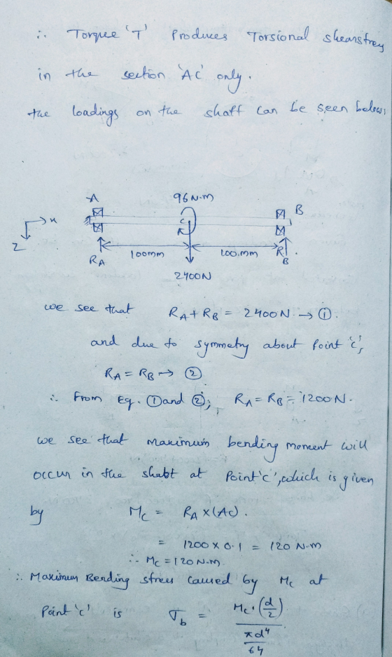
 The figure shows a transmission shaft. The steel solid shaft is 200 mm long between self-aligning bearings at A and B. Belt forces (in the same horizontal direction) are applied to a 120-mm diameter sheave at C. The left end of the shaft is connected to an electric motor attached to a clutch by means of a flexible coupling. Nothing is attached to the right end (it is free). Assuming the shaft has a constant diameter, d, (a) Perform the...
The figure shows a transmission shaft. The steel solid shaft is 200 mm long between self-aligning...
 The figure shows a transmission shaft. The steel solid shaft is 200 mm long between self-aligning bearings at A and B. Belt forces in the same horizontal direction) are applied to a 120-mm diameter sheave at C. The left end of the shaft is connected to an electric motor attached to a clutch by means of a flexible coupling. Nothing is attached to the right end (it is free). Assuming the shaft has a constant diameter, d. (a) Perform the...
For the shaft shown below, draw the free body diagram of just the shaft (isolated from...
 For the shaft shown below, draw the free body diagram of just
the shaft (isolated from the pulley) including directions and
values of all reaction loads at the self-aligning bearings A and B.
Once complete, directly under your FBD, draw the shear force
diagram (SFD), bending moment diagram (BMD) and torque diagram (TD)
with all important values shown on the figures. Directions are
critical and you must show your axes (choose).
B 100 Free end of shaft 20-mm- dia. shaft...
For the shaft shown below, draw the free body diagram of just
the shaft (isolated from the pulley) including directions and
values of all reaction loads at the self-aligning bearings A and B.
Once complete, directly under your FBD, draw the shear force
diagram (SFD), bending moment diagram (BMD) and torque diagram (TD)
with all important values shown on the figures. Directions are
critical and you must show your axes (choose).
B 100 Free end of shaft 20-mm- dia. shaft...
3. Power transmission is an important engineering application and relies on the integrity of the shaft designs. Assume a solid, circular steel shaft with a uniform diameter d 50 mm and a total le...
 3. Power transmission is an important engineering application and relies on the integrity of the shaft designs. Assume a solid, circular steel shaft with a uniform diameter d 50 mm and a total length I3 m. At its midpoint, a belt passes over a pulley and delivers 50 kW power to the shaft. This power is used to drive two machines at either end of the shaft. Machine 1 consumes P1 20 kW and machine 2 uses P230 KW. The...
Problem 1 (25 Points) Two solid steel (6-80 GPa) shafts are connected by the gears shown. Shaft (1) has a diameter of 45 mm, and shaft (2) has an outside diameter of 55 mm and wall thickness 4 mm...
 Problem 1 (25 Points) Two solid steel (6-80 GPa) shafts are connected by the gears shown. Shaft (1) has a diameter of 45 mm, and shaft (2) has an outside diameter of 55 mm and wall thickness 4 mm. Assume that the bearings shown allow free rotation of the shafts. If a 400 N-m torque is applied at gear D, determine (a) the maximum shear stress magnitudes in each shaft. (b) the angles of twist ф, and ф (c) the...
please solve with details Question#1140Marksl The shaft shown in the figure is rotating at 650 rpm and it receives 5592.75 W through a flexible coupling at its right end. The power is delivered t...
 please solve with details
Question#1140Marksl The shaft shown in the figure is rotating at 650 rpm and it receives 5592.75 W through a flexible coupling at its right end. The power is delivered to an adjacent shaft through a single helical gear B having a normal pressure angle of 20° and a helix angle of 15o. The pitch diameter for the gear is 105.1814 mm (4.141 in). A spacer is used to position the gear relative to bearing C. The...
please solve with details
Question#1140Marksl The shaft shown in the figure is rotating at 650 rpm and it receives 5592.75 W through a flexible coupling at its right end. The power is delivered to an adjacent shaft through a single helical gear B having a normal pressure angle of 20° and a helix angle of 15o. The pitch diameter for the gear is 105.1814 mm (4.141 in). A spacer is used to position the gear relative to bearing C. The...
 The figure shows a transmission shaft. The steel solid shaft is 200 mm long between self-aligning bearings at A and B. Belt forces (in the same horizontal direction) are applied to a 120-mm diameter sheave at C. The left end of the shaft is connected to an electric motor attached to a clutch by means of a flexible coupling. Nothing is attached to the right end (it is free). Assuming the shaft has a constant diameter, d, (a) Perform the...
 The figure shows a transmission shaft. The steel solid shaft is 200 mm long between self-aligning bearings at A and B. Belt forces in the same horizontal direction) are applied to a 120-mm diameter sheave at C. The left end of the shaft is connected to an electric motor attached to a clutch by means of a flexible coupling. Nothing is attached to the right end (it is free). Assuming the shaft has a constant diameter, d. (a) Perform the...
 For the shaft shown below, draw the free body diagram of just
the shaft (isolated from the pulley) including directions and
values of all reaction loads at the self-aligning bearings A and B.
Once complete, directly under your FBD, draw the shear force
diagram (SFD), bending moment diagram (BMD) and torque diagram (TD)
with all important values shown on the figures. Directions are
critical and you must show your axes (choose).
B 100 Free end of shaft 20-mm- dia. shaft...
For the shaft shown below, draw the free body diagram of just
the shaft (isolated from the pulley) including directions and
values of all reaction loads at the self-aligning bearings A and B.
Once complete, directly under your FBD, draw the shear force
diagram (SFD), bending moment diagram (BMD) and torque diagram (TD)
with all important values shown on the figures. Directions are
critical and you must show your axes (choose).
B 100 Free end of shaft 20-mm- dia. shaft...
 3. Power transmission is an important engineering application and relies on the integrity of the shaft designs. Assume a solid, circular steel shaft with a uniform diameter d 50 mm and a total length I3 m. At its midpoint, a belt passes over a pulley and delivers 50 kW power to the shaft. This power is used to drive two machines at either end of the shaft. Machine 1 consumes P1 20 kW and machine 2 uses P230 KW. The...
 Problem 1 (25 Points) Two solid steel (6-80 GPa) shafts are connected by the gears shown. Shaft (1) has a diameter of 45 mm, and shaft (2) has an outside diameter of 55 mm and wall thickness 4 mm. Assume that the bearings shown allow free rotation of the shafts. If a 400 N-m torque is applied at gear D, determine (a) the maximum shear stress magnitudes in each shaft. (b) the angles of twist ф, and ф (c) the...
 please solve with details
Question#1140Marksl The shaft shown in the figure is rotating at 650 rpm and it receives 5592.75 W through a flexible coupling at its right end. The power is delivered to an adjacent shaft through a single helical gear B having a normal pressure angle of 20° and a helix angle of 15o. The pitch diameter for the gear is 105.1814 mm (4.141 in). A spacer is used to position the gear relative to bearing C. The...
please solve with details
Question#1140Marksl The shaft shown in the figure is rotating at 650 rpm and it receives 5592.75 W through a flexible coupling at its right end. The power is delivered to an adjacent shaft through a single helical gear B having a normal pressure angle of 20° and a helix angle of 15o. The pitch diameter for the gear is 105.1814 mm (4.141 in). A spacer is used to position the gear relative to bearing C. The...
Most questions answered within 3 hours.
-
1. Which of the following statements is true of money?
It is anything accepted in exchange...
asked 12 seconds ago -
BASED ON THE AIRBNB, ETSY, UBER: GROWING FROM ONE THOUSAND TO
ONE MILLION CUSTOMERS HARVARD CASE:...
asked 26 minutes ago -
Which of these methods cause sterilization?
Autoclaving
Dry heat
Gamma irradiation
Ethylene oxide
A.
Yes
No...
asked 31 minutes ago -
A biologist wishes to estimate the effect of an antibiotic on
the growth of a particular...
asked 39 minutes ago -
O’Deesha Company has the following information available:
Quality engineering of
products
$20,000
Quality training of
employees &n
asked 47 minutes ago -
a) Draw two water molecules.
b) Clearly name and label the type of bond that exists...
asked 1 hour ago -
C - Language
Write a loop that sets each array element to the sum of itself...
asked 3 hours ago -
(63
#14)
which of the following statments best describes how chamging
the concentration of the substances...
asked 6 hours ago -
In the following reaction, which element is undergoing
oxidation: Na2SO3 + N2O --> N2 + Na2SO4...
asked 7 hours ago -
Which of the following pairs of ions have the same electron
configuration?
I: Br− and Se2−...
asked 10 hours ago -
The Foremost Composite Materials Company is planning a two-day
sales conference for October 19-20. The conference...
asked 10 hours ago -
3) Illustrate the observed pattern of relatedness of organisms
versus adaptations to specific conditions. This means...
asked 10 hours ago