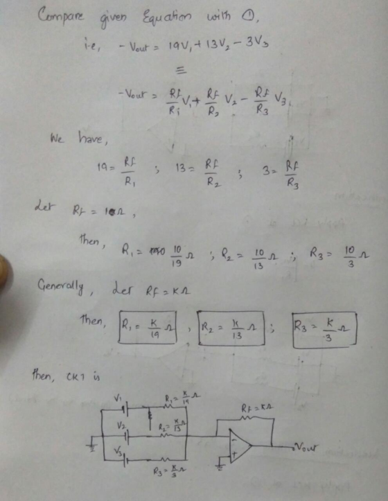
Design a circuit having an output given by: -Vout = 19V1 + 13V2 - 3V3
Design a circuit having an output given by: -Vout = 19V1 + 13V2 - 3V3
Homework Answers

Add Answer to:
Design a circuit having an output given by:
-Vout = 19V1 + 13V2 -
3V3
Design the below operational amplifier circuit having one output, Vout, and two inputs, V1 and V2....
 Design the below operational amplifier circuit having one output, Vout, and two inputs, V1 and V2. The output must be related to the inputs by Vout = 2 V1 - 9 V2 26 km 180 kn 180 kn Rik - R2 kn Determine the value of R1 and Rz. R2 = ko R2 =
Find the output vout in terms of Vnfor the circuit below I 2 mA 2 Vout...
 Find the output vout in terms of Vnfor the circuit below I 2 mA 2 Vout ideal V--5 V in 3 R.
Find the Vout in the circuit and explain steps Problem #6: Determine the output voltage Vout...
 Find the Vout in the circuit and explain steps
Problem #6: Determine the output voltage Vout in the circuit below. (be careful with polarities of voltage sources.....) 18ΚΩ 36ΚΩ 6ΚΩ 6ko Ε ΠΟ HTHEIHIBITI ΕΠΙΠΗ ΗΠΕΙ Η ΠΑΠΑΙΤΕΙΤΑΙ Η ΕΞΕΤΗ Η ΕΠΑΝΕΝΑ ΑΛΛΑΓΗΕ ΕΗΕΗΙΕΕΤΕΕΙΕΙ ΑΗΗΗΗΕΙΗ. ΤΕΤ ΤΕΚΩ ΠΗΓΗΗΗ Η ΗΗΗΗ 12kΩ ΠΑΡΚΟ 2ν + ν - ΤΑΠΗΤΗ ΠΗ ΗΤΑΝ Η ΤΕΧΝΗ ΤΟ 3ν 에 ΕΞΗΓΕΙ ΤΕΤΟΙΑ ΤΕΤΤΙΙΙΕ ΠΑΝΕΠΙΣΤΗ ΠΕΙΤΕ
Find the Vout in the circuit and explain steps
Problem #6: Determine the output voltage Vout in the circuit below. (be careful with polarities of voltage sources.....) 18ΚΩ 36ΚΩ 6ΚΩ 6ko Ε ΠΟ HTHEIHIBITI ΕΠΙΠΗ ΗΠΕΙ Η ΠΑΠΑΙΤΕΙΤΑΙ Η ΕΞΕΤΗ Η ΕΠΑΝΕΝΑ ΑΛΛΑΓΗΕ ΕΗΕΗΙΕΕΤΕΕΙΕΙ ΑΗΗΗΗΕΙΗ. ΤΕΤ ΤΕΚΩ ΠΗΓΗΗΗ Η ΗΗΗΗ 12kΩ ΠΑΡΚΟ 2ν + ν - ΤΑΠΗΤΗ ΠΗ ΗΤΑΝ Η ΤΕΧΝΗ ΤΟ 3ν 에 ΕΞΗΓΕΙ ΤΕΤΟΙΑ ΤΕΤΤΙΙΙΕ ΠΑΝΕΠΙΣΤΗ ΠΕΙΤΕ
Problem 3) There is a black-box circuit (X circuit) having three inputs and one output as...
 Problem 3) There is a black-box circuit (X circuit) having three inputs and one output as shown in Figure 3. In order to understand the operation of the circuit, three different input signals are applied to the circuit and the output is observed as given in the figure. Vi(t)=Sin 2000nt - Vz(t)=2Cos2000 X P Circuit -3Sin2000xt+10Cos 2000xt+ +3Sin 1000 Vs(t)=1.5Sin 1000 a) What is the function of the X circuit? b) Design the circuit by using ideal op amps and...
show steps please Find the output voltage Vout, and the current i, in the circuit in...
 show steps please
Find the output voltage Vout, and the current i, in the circuit in Fig.1 below. HINT: VA = 0. R2 10K 12 M R1 = 2K2 w Va 1V Vout R3 = 3K 12 Fig. 1
show steps please
Find the output voltage Vout, and the current i, in the circuit in Fig.1 below. HINT: VA = 0. R2 10K 12 M R1 = 2K2 w Va 1V Vout R3 = 3K 12 Fig. 1
5. For the CB amplifier circuit as shown below, calculate the output voltage Vout with an...
 5. For the CB amplifier circuit as shown below, calculate the output voltage Vout with an input of 2 mV from the generator. R 47 4F 1 uF M Vout 500 3.3 kg 10 kg SRL 10 kg 2mpP 47 FR 2 kg TI
Solve symbolically. 1.(4) With the following values, determine output voltage Vout for the following amplifier circuit....
 Solve symbolically.
1.(4) With the following values, determine output voltage Vout for the following amplifier circuit. Vin= Rin= R = - FOTO Vin to Vout
Solve symbolically.
1.(4) With the following values, determine output voltage Vout for the following amplifier circuit. Vin= Rin= R = - FOTO Vin to Vout
For the circuit shown below, design the values of R1 and R2 that will cause Vout-6 Vif VIv-9 V. If the resistors you chose have a tolerance of 1 %, what is the maximum and minimum values of Vout? Des...
 For the circuit shown below, design the values of R1 and R2 that will cause Vout-6 Vif VIv-9 V. If the resistors you chose have a tolerance of 1 %, what is the maximum and minimum values of Vout? Design R3 so that the LED will be properly lit, if IF=10 mA, VF-3 V and Vout-6 V Design equations from the data sheet: VOUT-1.25%(1+R2 R1) U1 OUT ININLT OUT R3 R1 V1 (R3) R1) ADJ LT317A D1 IN) R2 (R2)...
An engineer wants to design a circuit that has the following input/output voltage characteristics. The variable...
 An engineer wants to design a circuit that has the following input/output voltage characteristics. The variable input DC voltage source that the engineer uses has 0.5 kOhm internal resistance; in the laboratory various diodes (pn and Zener), resistors and various fixed DC voltages are available. The diodes cannot be assumed as "ideal" in the design. Sketch your circuit, show all your calculations, mathematical validations and give specifications of your selected circuit elements with their values [40]. Vout (V) 3 2...
2. The following RC circuit is given. Vout(t) R> c = = At t = 0,...
 2. The following RC circuit is given. Vout(t) R> c = = At t = 0, the switch closes. V is a constant voltage and Vout(0) = 0 V. Using natural frequencies method, find the output voltage, Vout(t) and plot it. Now, change the location of the capacitor, C, as shown below. Assume the voltage across the capacitor is 0 V at t = 0. How does Vout(t) change? Plot the waveform for Vout(t). Vout(t)
 Design the below operational amplifier circuit having one output, Vout, and two inputs, V1 and V2. The output must be related to the inputs by Vout = 2 V1 - 9 V2 26 km 180 kn 180 kn Rik - R2 kn Determine the value of R1 and Rz. R2 = ko R2 =
 Find the output vout in terms of Vnfor the circuit below I 2 mA 2 Vout ideal V--5 V in 3 R.
 Find the Vout in the circuit and explain steps
Problem #6: Determine the output voltage Vout in the circuit below. (be careful with polarities of voltage sources.....) 18ΚΩ 36ΚΩ 6ΚΩ 6ko Ε ΠΟ HTHEIHIBITI ΕΠΙΠΗ ΗΠΕΙ Η ΠΑΠΑΙΤΕΙΤΑΙ Η ΕΞΕΤΗ Η ΕΠΑΝΕΝΑ ΑΛΛΑΓΗΕ ΕΗΕΗΙΕΕΤΕΕΙΕΙ ΑΗΗΗΗΕΙΗ. ΤΕΤ ΤΕΚΩ ΠΗΓΗΗΗ Η ΗΗΗΗ 12kΩ ΠΑΡΚΟ 2ν + ν - ΤΑΠΗΤΗ ΠΗ ΗΤΑΝ Η ΤΕΧΝΗ ΤΟ 3ν 에 ΕΞΗΓΕΙ ΤΕΤΟΙΑ ΤΕΤΤΙΙΙΕ ΠΑΝΕΠΙΣΤΗ ΠΕΙΤΕ
Find the Vout in the circuit and explain steps
Problem #6: Determine the output voltage Vout in the circuit below. (be careful with polarities of voltage sources.....) 18ΚΩ 36ΚΩ 6ΚΩ 6ko Ε ΠΟ HTHEIHIBITI ΕΠΙΠΗ ΗΠΕΙ Η ΠΑΠΑΙΤΕΙΤΑΙ Η ΕΞΕΤΗ Η ΕΠΑΝΕΝΑ ΑΛΛΑΓΗΕ ΕΗΕΗΙΕΕΤΕΕΙΕΙ ΑΗΗΗΗΕΙΗ. ΤΕΤ ΤΕΚΩ ΠΗΓΗΗΗ Η ΗΗΗΗ 12kΩ ΠΑΡΚΟ 2ν + ν - ΤΑΠΗΤΗ ΠΗ ΗΤΑΝ Η ΤΕΧΝΗ ΤΟ 3ν 에 ΕΞΗΓΕΙ ΤΕΤΟΙΑ ΤΕΤΤΙΙΙΕ ΠΑΝΕΠΙΣΤΗ ΠΕΙΤΕ
 Problem 3) There is a black-box circuit (X circuit) having three inputs and one output as shown in Figure 3. In order to understand the operation of the circuit, three different input signals are applied to the circuit and the output is observed as given in the figure. Vi(t)=Sin 2000nt - Vz(t)=2Cos2000 X P Circuit -3Sin2000xt+10Cos 2000xt+ +3Sin 1000 Vs(t)=1.5Sin 1000 a) What is the function of the X circuit? b) Design the circuit by using ideal op amps and...
 show steps please
Find the output voltage Vout, and the current i, in the circuit in Fig.1 below. HINT: VA = 0. R2 10K 12 M R1 = 2K2 w Va 1V Vout R3 = 3K 12 Fig. 1
show steps please
Find the output voltage Vout, and the current i, in the circuit in Fig.1 below. HINT: VA = 0. R2 10K 12 M R1 = 2K2 w Va 1V Vout R3 = 3K 12 Fig. 1
 5. For the CB amplifier circuit as shown below, calculate the output voltage Vout with an input of 2 mV from the generator. R 47 4F 1 uF M Vout 500 3.3 kg 10 kg SRL 10 kg 2mpP 47 FR 2 kg TI
 Solve symbolically.
1.(4) With the following values, determine output voltage Vout for the following amplifier circuit. Vin= Rin= R = - FOTO Vin to Vout
Solve symbolically.
1.(4) With the following values, determine output voltage Vout for the following amplifier circuit. Vin= Rin= R = - FOTO Vin to Vout
 For the circuit shown below, design the values of R1 and R2 that will cause Vout-6 Vif VIv-9 V. If the resistors you chose have a tolerance of 1 %, what is the maximum and minimum values of Vout? Design R3 so that the LED will be properly lit, if IF=10 mA, VF-3 V and Vout-6 V Design equations from the data sheet: VOUT-1.25%(1+R2 R1) U1 OUT ININLT OUT R3 R1 V1 (R3) R1) ADJ LT317A D1 IN) R2 (R2)...
 An engineer wants to design a circuit that has the following input/output voltage characteristics. The variable input DC voltage source that the engineer uses has 0.5 kOhm internal resistance; in the laboratory various diodes (pn and Zener), resistors and various fixed DC voltages are available. The diodes cannot be assumed as "ideal" in the design. Sketch your circuit, show all your calculations, mathematical validations and give specifications of your selected circuit elements with their values [40]. Vout (V) 3 2...
 2. The following RC circuit is given. Vout(t) R> c = = At t = 0, the switch closes. V is a constant voltage and Vout(0) = 0 V. Using natural frequencies method, find the output voltage, Vout(t) and plot it. Now, change the location of the capacitor, C, as shown below. Assume the voltage across the capacitor is 0 V at t = 0. How does Vout(t) change? Plot the waveform for Vout(t). Vout(t)
Most questions answered within 3 hours.
-
mode field diameter (MFD) is an important parameter in
characterizing single mode fibre properties which takes...
asked 56 seconds ago -
Question 4: What is the significance of those strange
“36.79%” and “63.21%” numbers the procedure? That...
asked 6 minutes ago -
The US Census Bureau gathered data regarding yearly gas sales
for residents of different states. Wyoming...
asked 6 minutes ago -
Rules of implementation!:
You may NOT modify any of the files except Expression.java in
ANY way....
asked 8 minutes ago -
A person in a casino decides to play blackjack until he loses a
game, but he...
asked 9 minutes ago -
Arbitration of disputes under the purview of "lemon laws" under
state statute is:
not required by...
asked 21 minutes ago -
Describe three pieces of evidence that mitochondria and evolved
from symbiotic mutualisms between a eukaryote (or...
asked 29 minutes ago -
An AM transmitter with a carrier power of 20 kW is connected to
a 50 Ω...
asked 37 minutes ago -
JAVA
Beginnings of a paper-rock-scissors game.
Paper-rock-scissors is a game often used to make decisions.
There...
asked 42 minutes ago -
Consider a concept learning example of 5 attributes. Attributes
can take one of (5,3,2,2,6) values respectively....
asked 48 minutes ago -
Red light of wavelength 675 nm is incident on a slit of width
4.56 × 10⁻⁶...
asked 58 minutes ago -
An object 4.0 mm high is on the optical axis of two lenses with
focal lengths...
asked 54 minutes ago