

Homework Answers

Answer all parts to get 100% feedback !! Voc Rb Rs C1 VS Re =ce SRL...
 Answer all parts to get 100% feedback !!
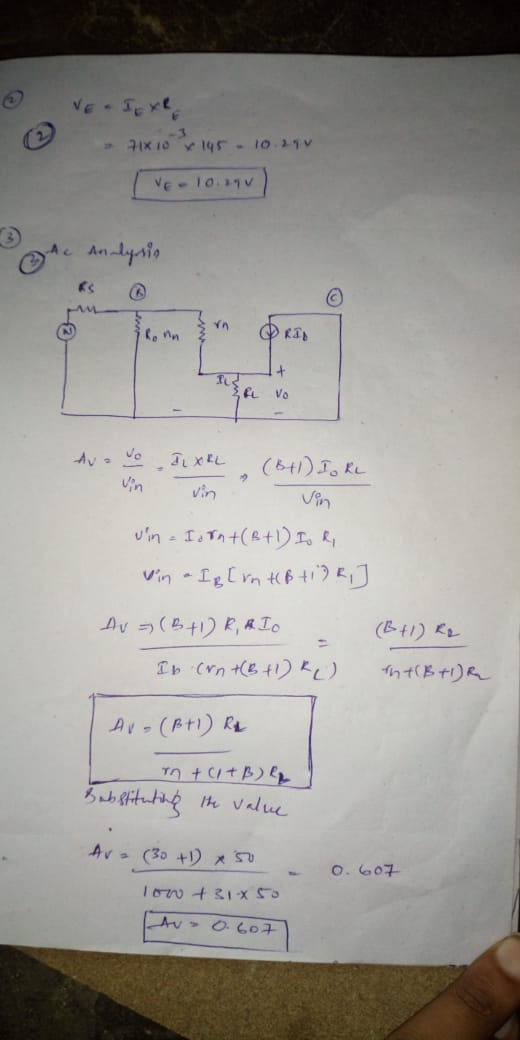
Voc Rb Rs C1 VS Re =ce SRL VO Figure 1 For the circuit of Figure 1 the following parameters are given with Vcc = 20 volts DC: Rs = 0 ohm C1 = 10 microfarads Ce = 0.1 microfarads rn = 1000 ohm gm = 30ms Re = 145 ohms Rb = 1750 ohms RL = 50 ohms C2 may be considered very large vs is a sinusoidal voltage source of...
Answer all parts to get 100% feedback !!
Voc Rb Rs C1 VS Re =ce SRL VO Figure 1 For the circuit of Figure 1 the following parameters are given with Vcc = 20 volts DC: Rs = 0 ohm C1 = 10 microfarads Ce = 0.1 microfarads rn = 1000 ohm gm = 30ms Re = 145 ohms Rb = 1750 ohms RL = 50 ohms C2 may be considered very large vs is a sinusoidal voltage source of...
Voc Ri Rc C2 + RS G Q2N3904 RL Vout 2 R2 RE CE Rin Rout...
 Voc Ri Rc C2 + RS G Q2N3904 RL Vout 2 R2 RE CE Rin Rout Cu B 1x B C o + V be : Cr 8m'be E VCC R R2 Rc RE RS RL С. Cz CE 12 V 8.2 kg 3.9 ko 6.3 k2 3.3 kΩ 3 ko 3.9 ko 10 uF 1uF 100 u Assume the 2N3904 has a 8 =100, Veron} = 0.7V, VA= 100V, C=100, C=13.9pF and Ce=8pF. Use the emission coefficient as n...
Vdd RL VO OL vin Rg ww The figure shows the circuit diagram of a common...
 Vdd RL VO OL vin Rg ww The figure shows the circuit diagram of a common source amplifier using a JFET supplied by an ideal sinusoidal signal source vin of variable frequency. The values of the circuit components are given as follows; Rg = 560k, RL = 1.5k, ro = infinity, C = 0.01 microfarads, gm = 7.0mA/Volt. At a frequency of 50 Hz it is determined that the magnitude of the gain vo/vin is nearest to which of the...
C- Amplifier: Consider figure 3. This circuit uses the JFET to amplify the input signal voltage F...
 C- Amplifier: Consider figure 3. This circuit uses the JFET to amplify the input signal voltage First the dc operation must be set. Use equation 1 and your previous data to calculate the value of Vas required to give I-0.5 mA. Determine the source resistance Rs needed to set this bias. Set up the circuit of figure 3 with your calculated value of Rs. Measure Vo and Vs to determine if your operating conditions are correct. Apply an input voltage...
Q.A. 2 -Statement: DC biasing of a CE amplifier circuit is as in Fig.2 Assume the...
 Q.A. 2 -Statement: DC biasing of a CE amplifier
circuit is as in Fig.2 Assume the parameters, VCC
= 12 volt, RE = 450 ohm; = 100; RL = 2250 ohm, RC =1000 ohm and
source resistance and Rs = 2500 ohm. Also, the device emitter
resistance re is negligible.
The amplifier is excited by a source, vs(t) = Vm × sin(2ft)
with Vm = 500 mV peak and f = 5500 Hz; and, coupling and by-pass
capacitors can...
Q.A. 2 -Statement: DC biasing of a CE amplifier
circuit is as in Fig.2 Assume the parameters, VCC
= 12 volt, RE = 450 ohm; = 100; RL = 2250 ohm, RC =1000 ohm and
source resistance and Rs = 2500 ohm. Also, the device emitter
resistance re is negligible.
The amplifier is excited by a source, vs(t) = Vm × sin(2ft)
with Vm = 500 mV peak and f = 5500 Hz; and, coupling and by-pass
capacitors can...
Assume the load resistor RL= 100 Ohms. Assume vS(t) = 1cos(wt). Rs=3ohms, L1=7H, L2=9H, and C=8uF...
 Assume the load resistor RL= 100
Ohms. Assume vS(t) =
1cos(wt). Rs=3ohms, L1=7H, L2=9H, and C=8uF
First, convert the circuit to an impedance equivalent circuit in
the phasor domain finding impedances in terms of w. Draw the
circuit and mark the impedances.
Then analyze the circuit (you will need to find equivalent
impedances and apply voltage division rule) to find the phasor
VL in terms of
VS, and find an expression for
g =
|VL|/|VS|,
the gain ratio of the...
Assume the load resistor RL= 100
Ohms. Assume vS(t) =
1cos(wt). Rs=3ohms, L1=7H, L2=9H, and C=8uF
First, convert the circuit to an impedance equivalent circuit in
the phasor domain finding impedances in terms of w. Draw the
circuit and mark the impedances.
Then analyze the circuit (you will need to find equivalent
impedances and apply voltage division rule) to find the phasor
VL in terms of
VS, and find an expression for
g =
|VL|/|VS|,
the gain ratio of the...
PLEASE SIMULATE IN PSPICE, OR MULTISIM, OR SIMILAR TOOL RC=10Kohm, RE=14.26Kohm RL=10Kohm, RB=10Kohm, R_sig = 50 ohms...
 PLEASE SIMULATE IN PSPICE, OR MULTISIM, OR SIMILAR TOOL
RC=10Kohm,
RE=14.26Kohm RL=10Kohm, RB=10Kohm, R_sig = 50
ohms
N, 42 R FIGURE L7.9: Common-emitter ampli fier circuit, with coupling capacitors, and resistor R for DC-biasing purposes. Based on Fig. 7.56 p. 470 S&S Ri
PLEASE SIMULATE IN PSPICE, OR MULTISIM, OR SIMILAR TOOL
RC=10Kohm,
RE=14.26Kohm RL=10Kohm, RB=10Kohm, R_sig = 50
ohms
N, 42 R FIGURE L7.9: Common-emitter ampli fier circuit, with coupling capacitors, and resistor R for DC-biasing purposes. Based on Fig. 7.56 p. 470 S&S Ri
RS Given that R2-40K, R5-10K, R6-10K, R7-10K, RL 5K, C 1-1 000uF, C3-. 1 uF, C4-1 000uF, C2-0pF and Vec=1 5V. Vcc C3 n RT Vin C1 vo Draw the DC model of this circuit. a. R6 RL Find the bias volta...
 RS Given that R2-40K, R5-10K, R6-10K, R7-10K, RL 5K, C 1-1 000uF, C3-. 1 uF, C4-1 000uF, C2-0pF and Vec=1 5V. Vcc C3 n RT Vin C1 vo Draw the DC model of this circuit. a. R6 RL Find the bias voltage at pin 3 of the op amp. b. ua741 R2 C4 Find the low-frequency cut-off of this circuit. c. acts like a short circuit? What is the input current at pin 2 of the op amp? e. f....
Q3. V CC R1 CL Rg R2 Vs Rs RL Figure -Q3 Consider the arrangement in...
 Q3. V CC R1 CL Rg R2 Vs Rs RL Figure -Q3 Consider the arrangement in the above Figure-Q3 circuit diagram i. Using the symbols under the usual notation, draw the high frequency equivalent ii. (6Marks) (9Marks) (5Marks) circuit diagram Find expressions for the voltage gain, input impedance and the output impedance Hence derive an expressionforthelowfrequency voltagegainoftheabove amplifier. iii.
Q2) Please show all working Thank you :) Question 2 (25 Marks) (a) (6 Marks) Bias...
 Q2)
Please show all working
Thank you :)
Question 2 (25 Marks) (a) (6 Marks) Bias the CE amplifier in Figure 2 to have IE = 1mA. Assume B-100, VBE(On) = 0.7 V, Vcc = 15V, VEE= -15V and RB = 100kQ. List all node voltages, currents and resistor values. (b) (10 Marks) Draw the small-signal model for the CE amplifier in Figure 2 Determine the input resistance, output resistance and gain of the amplifier. Assume VA = 100V, RL...
Q2)
Please show all working
Thank you :)
Question 2 (25 Marks) (a) (6 Marks) Bias the CE amplifier in Figure 2 to have IE = 1mA. Assume B-100, VBE(On) = 0.7 V, Vcc = 15V, VEE= -15V and RB = 100kQ. List all node voltages, currents and resistor values. (b) (10 Marks) Draw the small-signal model for the CE amplifier in Figure 2 Determine the input resistance, output resistance and gain of the amplifier. Assume VA = 100V, RL...
 Answer all parts to get 100% feedback !!
Voc Rb Rs C1 VS Re =ce SRL VO Figure 1 For the circuit of Figure 1 the following parameters are given with Vcc = 20 volts DC: Rs = 0 ohm C1 = 10 microfarads Ce = 0.1 microfarads rn = 1000 ohm gm = 30ms Re = 145 ohms Rb = 1750 ohms RL = 50 ohms C2 may be considered very large vs is a sinusoidal voltage source of...
Answer all parts to get 100% feedback !!
Voc Rb Rs C1 VS Re =ce SRL VO Figure 1 For the circuit of Figure 1 the following parameters are given with Vcc = 20 volts DC: Rs = 0 ohm C1 = 10 microfarads Ce = 0.1 microfarads rn = 1000 ohm gm = 30ms Re = 145 ohms Rb = 1750 ohms RL = 50 ohms C2 may be considered very large vs is a sinusoidal voltage source of...
 Voc Ri Rc C2 + RS G Q2N3904 RL Vout 2 R2 RE CE Rin Rout Cu B 1x B C o + V be : Cr 8m'be E VCC R R2 Rc RE RS RL С. Cz CE 12 V 8.2 kg 3.9 ko 6.3 k2 3.3 kΩ 3 ko 3.9 ko 10 uF 1uF 100 u Assume the 2N3904 has a 8 =100, Veron} = 0.7V, VA= 100V, C=100, C=13.9pF and Ce=8pF. Use the emission coefficient as n...
 Vdd RL VO OL vin Rg ww The figure shows the circuit diagram of a common source amplifier using a JFET supplied by an ideal sinusoidal signal source vin of variable frequency. The values of the circuit components are given as follows; Rg = 560k, RL = 1.5k, ro = infinity, C = 0.01 microfarads, gm = 7.0mA/Volt. At a frequency of 50 Hz it is determined that the magnitude of the gain vo/vin is nearest to which of the...
 C- Amplifier: Consider figure 3. This circuit uses the JFET to amplify the input signal voltage First the dc operation must be set. Use equation 1 and your previous data to calculate the value of Vas required to give I-0.5 mA. Determine the source resistance Rs needed to set this bias. Set up the circuit of figure 3 with your calculated value of Rs. Measure Vo and Vs to determine if your operating conditions are correct. Apply an input voltage...
 Q.A. 2 -Statement: DC biasing of a CE amplifier
circuit is as in Fig.2 Assume the parameters, VCC
= 12 volt, RE = 450 ohm; = 100; RL = 2250 ohm, RC =1000 ohm and
source resistance and Rs = 2500 ohm. Also, the device emitter
resistance re is negligible.
The amplifier is excited by a source, vs(t) = Vm × sin(2ft)
with Vm = 500 mV peak and f = 5500 Hz; and, coupling and by-pass
capacitors can...
Q.A. 2 -Statement: DC biasing of a CE amplifier
circuit is as in Fig.2 Assume the parameters, VCC
= 12 volt, RE = 450 ohm; = 100; RL = 2250 ohm, RC =1000 ohm and
source resistance and Rs = 2500 ohm. Also, the device emitter
resistance re is negligible.
The amplifier is excited by a source, vs(t) = Vm × sin(2ft)
with Vm = 500 mV peak and f = 5500 Hz; and, coupling and by-pass
capacitors can...
 Assume the load resistor RL= 100
Ohms. Assume vS(t) =
1cos(wt). Rs=3ohms, L1=7H, L2=9H, and C=8uF
First, convert the circuit to an impedance equivalent circuit in
the phasor domain finding impedances in terms of w. Draw the
circuit and mark the impedances.
Then analyze the circuit (you will need to find equivalent
impedances and apply voltage division rule) to find the phasor
VL in terms of
VS, and find an expression for
g =
|VL|/|VS|,
the gain ratio of the...
Assume the load resistor RL= 100
Ohms. Assume vS(t) =
1cos(wt). Rs=3ohms, L1=7H, L2=9H, and C=8uF
First, convert the circuit to an impedance equivalent circuit in
the phasor domain finding impedances in terms of w. Draw the
circuit and mark the impedances.
Then analyze the circuit (you will need to find equivalent
impedances and apply voltage division rule) to find the phasor
VL in terms of
VS, and find an expression for
g =
|VL|/|VS|,
the gain ratio of the...
 PLEASE SIMULATE IN PSPICE, OR MULTISIM, OR SIMILAR TOOL
RC=10Kohm,
RE=14.26Kohm RL=10Kohm, RB=10Kohm, R_sig = 50
ohms
N, 42 R FIGURE L7.9: Common-emitter ampli fier circuit, with coupling capacitors, and resistor R for DC-biasing purposes. Based on Fig. 7.56 p. 470 S&S Ri
PLEASE SIMULATE IN PSPICE, OR MULTISIM, OR SIMILAR TOOL
RC=10Kohm,
RE=14.26Kohm RL=10Kohm, RB=10Kohm, R_sig = 50
ohms
N, 42 R FIGURE L7.9: Common-emitter ampli fier circuit, with coupling capacitors, and resistor R for DC-biasing purposes. Based on Fig. 7.56 p. 470 S&S Ri
 RS Given that R2-40K, R5-10K, R6-10K, R7-10K, RL 5K, C 1-1 000uF, C3-. 1 uF, C4-1 000uF, C2-0pF and Vec=1 5V. Vcc C3 n RT Vin C1 vo Draw the DC model of this circuit. a. R6 RL Find the bias voltage at pin 3 of the op amp. b. ua741 R2 C4 Find the low-frequency cut-off of this circuit. c. acts like a short circuit? What is the input current at pin 2 of the op amp? e. f....
 Q3. V CC R1 CL Rg R2 Vs Rs RL Figure -Q3 Consider the arrangement in the above Figure-Q3 circuit diagram i. Using the symbols under the usual notation, draw the high frequency equivalent ii. (6Marks) (9Marks) (5Marks) circuit diagram Find expressions for the voltage gain, input impedance and the output impedance Hence derive an expressionforthelowfrequency voltagegainoftheabove amplifier. iii.
 Q2)
Please show all working
Thank you :)
Question 2 (25 Marks) (a) (6 Marks) Bias the CE amplifier in Figure 2 to have IE = 1mA. Assume B-100, VBE(On) = 0.7 V, Vcc = 15V, VEE= -15V and RB = 100kQ. List all node voltages, currents and resistor values. (b) (10 Marks) Draw the small-signal model for the CE amplifier in Figure 2 Determine the input resistance, output resistance and gain of the amplifier. Assume VA = 100V, RL...
Q2)
Please show all working
Thank you :)
Question 2 (25 Marks) (a) (6 Marks) Bias the CE amplifier in Figure 2 to have IE = 1mA. Assume B-100, VBE(On) = 0.7 V, Vcc = 15V, VEE= -15V and RB = 100kQ. List all node voltages, currents and resistor values. (b) (10 Marks) Draw the small-signal model for the CE amplifier in Figure 2 Determine the input resistance, output resistance and gain of the amplifier. Assume VA = 100V, RL...
Most questions answered within 3 hours.
-
You are attempting to calculate a firm’s free cash flow to
equity. You know the following...
asked 33 minutes ago -
the following reaction occurs in a balloon containing
N2O2 gas
N2O4(g)=2NO2(g)
will the volume of the...
asked 1 hour ago -
answer the questions throughout this program
public class Day implements Comparable {
Private Boolean atWork;...
asked 1 hour ago -
This is C++ code for parking fee management program
#include <iostream>
#include <iomanip>
using namespace std;...
asked 1 hour ago -
The free energy change for the following reaction at 25 °C, when
[Sn2+] = 1.17 M...
asked 3 hours ago -
An MNE is this kind of industry when competition in one country
is essentially independent of...
asked 4 hours ago -
. For this set of questions, determine what
proportion of a normal distribution is located betweeneach...
asked 5 hours ago -
A college student is employed as a door-to-door newspaper
salesman. Historical data suggests that the student...
asked 6 hours ago -
MATLAB HW 11 problem using Switch Case and Input commands
Write a script file that calculates...
asked 5 hours ago -
Considering gravitational time dilation, calculate the time that
passes in Earth’s surface while 1 hour passes...
asked 6 hours ago -
Minitab Problem: Take the Lake Hume June rainfall data and find
use the processes outlined in...
asked 7 hours ago -
X Company is trying to decide whether to continue using old
equipment to make Product A...
asked 7 hours ago