

Homework Answers


Add Answer to:
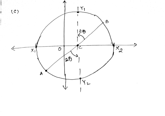
3. The states of stress at two points in a loaded beam are represented in Fig....
Consider the given state of stress. Take X = 10 MPa and Y = 45 MPa....
 Consider the given state of stress. Take X = 10 MPa and
Y = 45 MPa.
Determine the principal planes using Mohr's circle. a) The
principal planes are at − ° and °.
Determine the principal stresses using Mohr's circle. b)The
minimum principal stress is − MPa, and the maximum
principal stress is MPa.
Determine the orientation of the planes of maximum in-plane
shearing stress using Mohr's circle. c) The orientation of the
plane of maximum in-plane shearing stress in the first quadrant
is °....
Consider the given state of stress. Take X = 10 MPa and
Y = 45 MPa.
Determine the principal planes using Mohr's circle. a) The
principal planes are at − ° and °.
Determine the principal stresses using Mohr's circle. b)The
minimum principal stress is − MPa, and the maximum
principal stress is MPa.
Determine the orientation of the planes of maximum in-plane
shearing stress using Mohr's circle. c) The orientation of the
plane of maximum in-plane shearing stress in the first quadrant
is °....
40 M 45 MP 50 MPA - For the given state of stress, Part A: determine...
 40 M 45 MP 50 MPA - For the given state of stress, Part A: determine analytically (using stress transformation equations): 1) the principal planes. 2) the principal stresses. 3) Sketch the stress element for the above condition 4) the orientation of the planes of maximum in-plane shearing stress, 5) the maximum in-plane shearing stress and the corresponding normal stress. 6) Sketch the stress element for the above condition Part B: Only use Mohr's circle to determine 1) the principal...
2. A structural steel beam is loaded in such a way that a stress block is...
 2. A structural steel beam is loaded in such a way that a stress block is subjected to the stresses shown in Figure 2. Solve the problem using Mohr's circle drawn on a piece of graph paper with coordinates for all relevant points. Determine the in-plane principal stresses and the angle of orientation. Show your results on a stress block. Determine the maximum in-plane shear stress, the normal stresses, and the angle of orientation. Show your results on a stress...
your Consider the element in plane stress as shown below. () (2 points) Draw corresponding Mohr's...
 your Consider the element in plane stress as shown below. () (2 points) Draw corresponding Mohr's circle coordinate axes with appropriate labels, center point A. radius of the circle (1) (3 points) Using the Mohir's circle, find the magnitude of the principal stresses and principal directions. Show them on a sketch of a properly oriented clement (c) (3 points) Using the Mohr's circle, find the magnitude of the maximun shear stress and associated normal stresses Show them on a sketch...
I need part b please 40 M 45 MP 50 MPA - For the given state...
 I need part b please
40 M 45 MP 50 MPA - For the given state of stress, Part A: determine analytically (using stress transformation equations): 1) the principal planes. 2) the principal stresses. 3) Sketch the stress element for the above condition 4) the orientation of the planes of maximum in-plane shearing stress, 5) the maximum in-plane shearing stress and the corresponding normal stress. 6) Sketch the stress element for the above condition Part B: Only use Mohr's circle...
I need part b please
40 M 45 MP 50 MPA - For the given state of stress, Part A: determine analytically (using stress transformation equations): 1) the principal planes. 2) the principal stresses. 3) Sketch the stress element for the above condition 4) the orientation of the planes of maximum in-plane shearing stress, 5) the maximum in-plane shearing stress and the corresponding normal stress. 6) Sketch the stress element for the above condition Part B: Only use Mohr's circle...
3. Figure shows a state of plane stress consists of normal stresses 60 MPa and Ly-40MPa;...
 3. Figure shows a state of plane stress consists of normal stresses 60 MPa and Ly-40MPa; and unknown shear stress, The maximum principal stress was determined to be 104.34 MPa. Using Mohr's cirdle, determine a. the magnitude of the shear stress, b. the principal plane and the minimum principal stress. Then, sketch the element showing all stresses in its proper orientation, c. the maximum shear stress, associated normal stress and the orientation of the element. Then, sketch the element showing...
The state of plane stress at a point under the surface of the ANKA airplane wing...
 The state of plane stress at a point under the surface of the ANKA airplane wing is represented on the element oriented as shown in the Figure. Deternine principal Stresses Calculate the maximum in-plane shear stress and associated average normal stress by using the analytical method and Mohr's circle. For each case, determine the corresponding orientation of the element with respect to the element shown and sketch the state of stress on the element. Determine the absolute maximum shear stress...
A state of plane stress consists of a tensile stress of ox=3 MPa, 0,=5 MPa, and...
 A state of plane stress consists of a tensile stress of ox=3 MPa, 0,=5 MPa, and txy=-7 MPa a. Draw the original unrotated element and the corresponding 2-D Mohr's circle construction showing the x-face and y-face coordinates. b. Calculate the principal stresses, o, and O2 and their corresponding principal angles, 0p1,0p2 and show all of these on your Mohr's circle construction and a properly oriented stress element c. Calculate the maximum shear stresses, ITmax and their corresponding angles of maximum...
A state of plane stress consists of a tensile stress of ox=3 MPa, 0,=5 MPa, and...
 A state of plane stress consists of a tensile stress of ox=3 MPa, 0,=5 MPa, and Txy=-7 MPa a. Draw the original unrotated element and the corresponding 2-D Mohr's circle construction showing the x-face and y-face coordinates. b. Calculate the principal stresses, 01 and 02 and their corresponding principal angles, 021,092 and show all of these on your Mohr's circle construction and a properly oriented stress element. c. Calculate the maximum shear stresses, ETmax and their corresponding angles of maximum...
 Consider the given state of stress. Take X = 10 MPa and
Y = 45 MPa.
Determine the principal planes using Mohr's circle. a) The
principal planes are at − ° and °.
Determine the principal stresses using Mohr's circle. b)The
minimum principal stress is − MPa, and the maximum
principal stress is MPa.
Determine the orientation of the planes of maximum in-plane
shearing stress using Mohr's circle. c) The orientation of the
plane of maximum in-plane shearing stress in the first quadrant
is °....
Consider the given state of stress. Take X = 10 MPa and
Y = 45 MPa.
Determine the principal planes using Mohr's circle. a) The
principal planes are at − ° and °.
Determine the principal stresses using Mohr's circle. b)The
minimum principal stress is − MPa, and the maximum
principal stress is MPa.
Determine the orientation of the planes of maximum in-plane
shearing stress using Mohr's circle. c) The orientation of the
plane of maximum in-plane shearing stress in the first quadrant
is °....
 40 M 45 MP 50 MPA - For the given state of stress, Part A: determine analytically (using stress transformation equations): 1) the principal planes. 2) the principal stresses. 3) Sketch the stress element for the above condition 4) the orientation of the planes of maximum in-plane shearing stress, 5) the maximum in-plane shearing stress and the corresponding normal stress. 6) Sketch the stress element for the above condition Part B: Only use Mohr's circle to determine 1) the principal...
 40 M 45 MP 50 MPA - For the given state of stress, Part A: determine analytically (using stress transformation equations): 1) the principal planes. 2) the principal stresses. 3) Sketch the stress element for the above condition 4) the orientation of the planes of maximum in-plane shearing stress, 5) the maximum in-plane shearing stress and the corresponding normal stress. 6) Sketch the stress element for the above condition Part B: Only use Mohr's circle to determine 1) the principal...
 2. A structural steel beam is loaded in such a way that a stress block is subjected to the stresses shown in Figure 2. Solve the problem using Mohr's circle drawn on a piece of graph paper with coordinates for all relevant points. Determine the in-plane principal stresses and the angle of orientation. Show your results on a stress block. Determine the maximum in-plane shear stress, the normal stresses, and the angle of orientation. Show your results on a stress...
 your Consider the element in plane stress as shown below. () (2 points) Draw corresponding Mohr's circle coordinate axes with appropriate labels, center point A. radius of the circle (1) (3 points) Using the Mohir's circle, find the magnitude of the principal stresses and principal directions. Show them on a sketch of a properly oriented clement (c) (3 points) Using the Mohr's circle, find the magnitude of the maximun shear stress and associated normal stresses Show them on a sketch...
 I need part b please
40 M 45 MP 50 MPA - For the given state of stress, Part A: determine analytically (using stress transformation equations): 1) the principal planes. 2) the principal stresses. 3) Sketch the stress element for the above condition 4) the orientation of the planes of maximum in-plane shearing stress, 5) the maximum in-plane shearing stress and the corresponding normal stress. 6) Sketch the stress element for the above condition Part B: Only use Mohr's circle...
I need part b please
40 M 45 MP 50 MPA - For the given state of stress, Part A: determine analytically (using stress transformation equations): 1) the principal planes. 2) the principal stresses. 3) Sketch the stress element for the above condition 4) the orientation of the planes of maximum in-plane shearing stress, 5) the maximum in-plane shearing stress and the corresponding normal stress. 6) Sketch the stress element for the above condition Part B: Only use Mohr's circle...
 3. Figure shows a state of plane stress consists of normal stresses 60 MPa and Ly-40MPa; and unknown shear stress, The maximum principal stress was determined to be 104.34 MPa. Using Mohr's cirdle, determine a. the magnitude of the shear stress, b. the principal plane and the minimum principal stress. Then, sketch the element showing all stresses in its proper orientation, c. the maximum shear stress, associated normal stress and the orientation of the element. Then, sketch the element showing...
 The state of plane stress at a point under the surface of the ANKA airplane wing is represented on the element oriented as shown in the Figure. Deternine principal Stresses Calculate the maximum in-plane shear stress and associated average normal stress by using the analytical method and Mohr's circle. For each case, determine the corresponding orientation of the element with respect to the element shown and sketch the state of stress on the element. Determine the absolute maximum shear stress...
 A state of plane stress consists of a tensile stress of ox=3 MPa, 0,=5 MPa, and txy=-7 MPa a. Draw the original unrotated element and the corresponding 2-D Mohr's circle construction showing the x-face and y-face coordinates. b. Calculate the principal stresses, o, and O2 and their corresponding principal angles, 0p1,0p2 and show all of these on your Mohr's circle construction and a properly oriented stress element c. Calculate the maximum shear stresses, ITmax and their corresponding angles of maximum...
 A state of plane stress consists of a tensile stress of ox=3 MPa, 0,=5 MPa, and Txy=-7 MPa a. Draw the original unrotated element and the corresponding 2-D Mohr's circle construction showing the x-face and y-face coordinates. b. Calculate the principal stresses, 01 and 02 and their corresponding principal angles, 021,092 and show all of these on your Mohr's circle construction and a properly oriented stress element. c. Calculate the maximum shear stresses, ETmax and their corresponding angles of maximum...
Most questions answered within 3 hours.
-
Write a program to solve the Josephus problem, with the following
modification:
Sample Input:
./a.out n...
asked 1 hour ago -
At the start of a CD it is spinning at a rate of 525 rpm
(revolutions...
asked 2 hours ago -
4. Without doing any calculations, predict whether the observed
∆T would increase, decrease or remain the...
asked 3 hours ago -
Based on the range, which of the following sets of scores has
the greatest variability? 3,...
asked 4 hours ago -
Ripples in a pond travel at a velocity of 3 m/s with one peak
passing a...
asked 4 hours ago -
A man stands on the roof of a building of height 13.0 mm and
throws a...
asked 4 hours ago -
The extent to which assets are financed by borrowed funds and
other liabilities is indicated by:...
asked 5 hours ago -
Explain in detail
Germany is the fifth largest economy
explain what goods and services Germany specializes...
asked 5 hours ago -
The density of platinum is 21.45 g/mL. If a cube of platinum
with a mass of...
asked 5 hours ago -
Accounts Receivable
Sales
A/R Posting
Extended Sales Invoice
Packing Slip
Compare invoice to packing slip 2...
asked 5 hours ago -
Michaella, age 23, is a full-time law student and is claimed by
her parents as a...
asked 5 hours ago -
Why are polymers not typically casted into products?
asked 6 hours ago