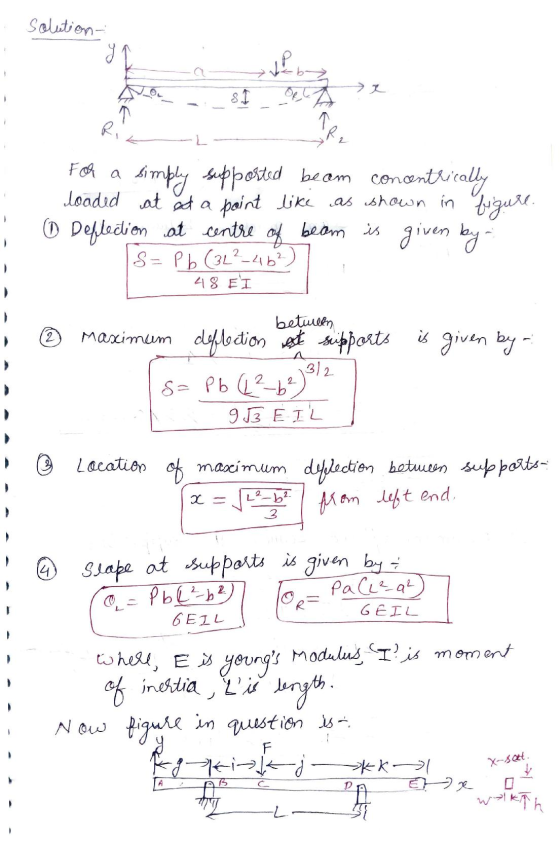
![{ F kg>k X-SECT *—→ ]X A 口 p张个 h Dimensions and Loads: i g k W h F i 0.85 ft 0.95 ft 3.13 ft 1.42 ft 1 in 1.625 in 2.1 Kip](http://img.homeworklib.com/questions/c813f940-b962-11eb-a96e-b3a13fe1dc40.png?x-oss-process=image/resize,w_560)
Problem Statement:
An 6061 wrought aluminum beam is loaded and supported as shown.
Find the following, and neglecting the effect of self-weight.
(a) The deflection of the beam midway between the
supports.
(b) The maximum deflection between the supports.
(c) The location of the maximum deflection between the
supports.
(d) The deflection of the beam at point A.
(e) The deflection of the beam at point E.
(f) The factor of safety against yielding for the beams maximum
flexural stress.

Answers:
(Denote upward deflections with positive values, and downward
deflections with negative values. Denote positive slopes with
positive values and negative slopes with negative values.)
Homework Answers


Add Answer to:
Problem Statement:
An 6061 wrought aluminum beam is loaded and supported as shown.
Find the following,...
4) A 100 foot long simply-supported bridge girder supports the unfactored loads shown in the figure....
 4) A 100 foot long simply-supported bridge girder supports the unfactored loads shown in the figure. The uniformly distributed dead load, wD, includes the self weight of the girder, and is constant along the full beam length. Concentrated live loads, PL, are applied as shown in the figure. a) Draw factored shear force and factored bending moment diagrams in the spaces provided. Show magnitudes at locations A, B, C, D and E on each diagram.(8) PL = 50k PL-50k WD-2.5...
(9 points) Difficulty (3/5) A S20x75 I-beam is loaded and supported as shown, with F =...
 (9 points) Difficulty (3/5) A S20x75 I-beam is loaded and supported as shown, with F = 7.8 kip. The dirmensions on the figure are a = 5 6 ft and b 1.96 ft Accounting for the self weight of the beam, determine the reactions at the support and the maximum stress in the beam. Report upward forces and counter-clockwise moments as positive and downward forces and clock-wise moments as negative. Report your stress as a psoitive value Answers: Rpall Muall
A timber [E = 1,800 ksi] beam is loaded and supported as shown. The cross section...
 A timber [E = 1,800 ksi] beam is loaded and supported
as shown. The cross section of the timber beam is b = 4
in. wide and h = 7 in. deep. The beam is supported at
B by a 0.875-in.-diameter aluminum [E = 10,500
ksi] rod, which has no load before the distributed load is applied
to the beam. After a distributed load of w = 610 lb/ft is
applied to the beam, determine
(a) the force carried by...
A timber [E = 1,800 ksi] beam is loaded and supported
as shown. The cross section of the timber beam is b = 4
in. wide and h = 7 in. deep. The beam is supported at
B by a 0.875-in.-diameter aluminum [E = 10,500
ksi] rod, which has no load before the distributed load is applied
to the beam. After a distributed load of w = 610 lb/ft is
applied to the beam, determine
(a) the force carried by...
A) The internal span CD on a continuous beam is deflected as shown (Figure 2) as...
 A) The internal span CD on a continuous beam is deflected as
shown (Figure 2) as a result of loads on other portions of the
beam, where L = 25 ft , α = 0.75 ∘, β = 0.35 ∘, E =
2.9×10⁴ ksi , and I = 1500 in4 . There is no vertical
deflection at either end. What is the internal moment at D?
M_D
B)The end span EF on a continuous beam is deflected as shown
(Figure...
A) The internal span CD on a continuous beam is deflected as
shown (Figure 2) as a result of loads on other portions of the
beam, where L = 25 ft , α = 0.75 ∘, β = 0.35 ∘, E =
2.9×10⁴ ksi , and I = 1500 in4 . There is no vertical
deflection at either end. What is the internal moment at D?
M_D
B)The end span EF on a continuous beam is deflected as shown
(Figure...
Use the graphical method to construct the shear-force and bending-moment diagrams for the beam shown. Let...
 Use the graphical method to construct the shear-force and bending-moment diagrams for the beam shown. Let a=4.0 ft, b=9.0 ft, c=5.0 ft, d=4.0 ft, w = 8 kips/ft and P = 75 kips. Construct the shear-force and bending-moment diagrams on paper and use the results to answer the questions in the subsequent parts of this GO exercise. W X A B C D E a b с For this loading, calculate the reaction forces Ay and Ey acting on the...
A loaded beam with a pin support at B and a rller support at C is shown in Figure 1. The applied loads on the bea...
 A loaded beam with a pin support at B and a rller support at C is shown in Figure 1. The applied loads on the beam are: an anti-clockwise point moment at A, a variably distributed load between B and C, and a clockwise point moment at D g kN/m f kNm h kN m A C 4 m 2 m 2 m Figure 1 The magnitude of the anti-clockwise point moment f in units of kN'm can be found...
Problem 2 (65%) (see table on page 2 for values of Wu(AB) and W (AC) Two...
 Problem 2 (65%) (see table on page 2 for values of Wu(AB) and W (AC) Two simply supported beams meet at the corner 16 foot tall beam-column "A" shown. Beam AB carries supports a uniformly distributed factored design load W AB)=?? and is 24 feet long. Beam AC carries a uniformly distributed load, W.AC=?? and is 16 feet long. Compute the following if the beams and the beam-column are laterally supported at the ends only in this braced frame. a)...
q= 5 p= 20 The simple concrete beam shown in the figure has a cross section...
 q= 5
p= 20
The simple concrete beam shown in the figure has a
cross section of 450x700 mm2 and knowing that the maximum
capacities of the concrete are those shown in the attached table
determine: A. The reactions in supports A and D. (table 1 and 2) B.
The bending moment equation. C. The corresponding values in table
3 D. The shear force equation. E. The corresponding values in
Table 4 F. The shear force diagram. (Draw the values...
q= 5
p= 20
The simple concrete beam shown in the figure has a
cross section of 450x700 mm2 and knowing that the maximum
capacities of the concrete are those shown in the attached table
determine: A. The reactions in supports A and D. (table 1 and 2) B.
The bending moment equation. C. The corresponding values in table
3 D. The shear force equation. E. The corresponding values in
Table 4 F. The shear force diagram. (Draw the values...
Problem 10.19 Consider the frame shown in (Figure 1). Assume the support at A is fixed...
 Problem 10.19 Consider the frame shown in (Figure 1). Assume the support at A is fixed and C is a pin. EI is constant. Part A Determine the internal end moment MBA acting on member AB of the frame at B measured clockwise. Express your answer using three significant figures. Enter positive value if the moment is clockwise and negative value if the moment is counterclockwise. MBA = 40.8 k ft Submit Previous Answers Correct Part B Determine the internal...
PartA Il Review Determine the moment MBA acting on member AB at B measured clockwise. Express...
 PartA Il Review Determine the moment MBA acting on member AB at B measured clockwise. Express your answer using three significant figures. Enter positive value if the moment is clockwise and negative value if the moment is Consider the frame shown in (Figure 1). Assume the supports at A B, and D are fixed. EI is constant. Vecto uthbe reg Geet keyboard shotbuts hei MBA Submit Part B Determine the moment MBC acting on member BC at B measured clockwise....
 4) A 100 foot long simply-supported bridge girder supports the unfactored loads shown in the figure. The uniformly distributed dead load, wD, includes the self weight of the girder, and is constant along the full beam length. Concentrated live loads, PL, are applied as shown in the figure. a) Draw factored shear force and factored bending moment diagrams in the spaces provided. Show magnitudes at locations A, B, C, D and E on each diagram.(8) PL = 50k PL-50k WD-2.5...
 (9 points) Difficulty (3/5) A S20x75 I-beam is loaded and supported as shown, with F = 7.8 kip. The dirmensions on the figure are a = 5 6 ft and b 1.96 ft Accounting for the self weight of the beam, determine the reactions at the support and the maximum stress in the beam. Report upward forces and counter-clockwise moments as positive and downward forces and clock-wise moments as negative. Report your stress as a psoitive value Answers: Rpall Muall
 A timber [E = 1,800 ksi] beam is loaded and supported
as shown. The cross section of the timber beam is b = 4
in. wide and h = 7 in. deep. The beam is supported at
B by a 0.875-in.-diameter aluminum [E = 10,500
ksi] rod, which has no load before the distributed load is applied
to the beam. After a distributed load of w = 610 lb/ft is
applied to the beam, determine
(a) the force carried by...
A timber [E = 1,800 ksi] beam is loaded and supported
as shown. The cross section of the timber beam is b = 4
in. wide and h = 7 in. deep. The beam is supported at
B by a 0.875-in.-diameter aluminum [E = 10,500
ksi] rod, which has no load before the distributed load is applied
to the beam. After a distributed load of w = 610 lb/ft is
applied to the beam, determine
(a) the force carried by...
 A) The internal span CD on a continuous beam is deflected as
shown (Figure 2) as a result of loads on other portions of the
beam, where L = 25 ft , α = 0.75 ∘, β = 0.35 ∘, E =
2.9×10⁴ ksi , and I = 1500 in4 . There is no vertical
deflection at either end. What is the internal moment at D?
M_D
B)The end span EF on a continuous beam is deflected as shown
(Figure...
A) The internal span CD on a continuous beam is deflected as
shown (Figure 2) as a result of loads on other portions of the
beam, where L = 25 ft , α = 0.75 ∘, β = 0.35 ∘, E =
2.9×10⁴ ksi , and I = 1500 in4 . There is no vertical
deflection at either end. What is the internal moment at D?
M_D
B)The end span EF on a continuous beam is deflected as shown
(Figure...
 Use the graphical method to construct the shear-force and bending-moment diagrams for the beam shown. Let a=4.0 ft, b=9.0 ft, c=5.0 ft, d=4.0 ft, w = 8 kips/ft and P = 75 kips. Construct the shear-force and bending-moment diagrams on paper and use the results to answer the questions in the subsequent parts of this GO exercise. W X A B C D E a b с For this loading, calculate the reaction forces Ay and Ey acting on the...
 A loaded beam with a pin support at B and a rller support at C is shown in Figure 1. The applied loads on the beam are: an anti-clockwise point moment at A, a variably distributed load between B and C, and a clockwise point moment at D g kN/m f kNm h kN m A C 4 m 2 m 2 m Figure 1 The magnitude of the anti-clockwise point moment f in units of kN'm can be found...
 Problem 2 (65%) (see table on page 2 for values of Wu(AB) and W (AC) Two simply supported beams meet at the corner 16 foot tall beam-column "A" shown. Beam AB carries supports a uniformly distributed factored design load W AB)=?? and is 24 feet long. Beam AC carries a uniformly distributed load, W.AC=?? and is 16 feet long. Compute the following if the beams and the beam-column are laterally supported at the ends only in this braced frame. a)...
 q= 5
p= 20
The simple concrete beam shown in the figure has a
cross section of 450x700 mm2 and knowing that the maximum
capacities of the concrete are those shown in the attached table
determine: A. The reactions in supports A and D. (table 1 and 2) B.
The bending moment equation. C. The corresponding values in table
3 D. The shear force equation. E. The corresponding values in
Table 4 F. The shear force diagram. (Draw the values...
q= 5
p= 20
The simple concrete beam shown in the figure has a
cross section of 450x700 mm2 and knowing that the maximum
capacities of the concrete are those shown in the attached table
determine: A. The reactions in supports A and D. (table 1 and 2) B.
The bending moment equation. C. The corresponding values in table
3 D. The shear force equation. E. The corresponding values in
Table 4 F. The shear force diagram. (Draw the values...
 Problem 10.19 Consider the frame shown in (Figure 1). Assume the support at A is fixed and C is a pin. EI is constant. Part A Determine the internal end moment MBA acting on member AB of the frame at B measured clockwise. Express your answer using three significant figures. Enter positive value if the moment is clockwise and negative value if the moment is counterclockwise. MBA = 40.8 k ft Submit Previous Answers Correct Part B Determine the internal...
 PartA Il Review Determine the moment MBA acting on member AB at B measured clockwise. Express your answer using three significant figures. Enter positive value if the moment is clockwise and negative value if the moment is Consider the frame shown in (Figure 1). Assume the supports at A B, and D are fixed. EI is constant. Vecto uthbe reg Geet keyboard shotbuts hei MBA Submit Part B Determine the moment MBC acting on member BC at B measured clockwise....
Most questions answered within 3 hours.
-
Asked if he has any regrets about the way he's handled the
coronavirus crisis so far,...
asked 6 minutes ago -
True or False?
Considering a door as a rigid body. Its angular motion happens
in a...
asked 9 minutes ago -
In
IUPAC naming, do we concider the prefix in alphabatizing?
In other words do we look...
asked 15 minutes ago -
If a trust has income required to be distributed of $11,500,
other amounts paid or required...
asked 31 minutes ago -
The degree of ionization of a weak acid
____________________.
Select all that are True.
a) varies...
asked 31 minutes ago -
Cereal for Breakfast. A cereal company claims
70% of Americans start the day with cereal for...
asked 31 minutes ago -
An elevator has a placard stating that the maximum capacity is
2400 lblong dash15 passengers. So,...
asked 34 minutes ago -
two charged proteins P1 and P2 are located at the positions
(1m,1m) and (-1m,1m) respectively on...
asked 45 minutes ago -
eBook
Calculator
Job Order Cost Sheet
Remnant Carpet Company sells and installs commercial carpeting
for office...
asked 50 minutes ago -
Using Kapustinskii equation, determine the lattice energy of a
hypothetical compound NaCl2 . Assume the sum...
asked 52 minutes ago -
Most schools and
businesses require some standard style of documentation for written
reports. Discuss why might...
asked 49 minutes ago -
cookbooks are going metric. in such books 1 cup is equal to 240
ml. Express 1...
asked 52 minutes ago