

Homework Answers

Add Answer to:
Problem 1)-4): Structures are shown in the figures 1)-4) 1) Draw all the FBDs for your...
Problem 1-3 Structures are shown in the figures 1)-3) 1) Draw all the FBDs for your...
 Problem 1-3 Structures are shown in the figures 1)-3) 1) Draw all the FBDs for your calculation; 2) Determine the reactions at the support; 3) Draw shear and moment diagrams using the graphical method we discussed in today's class; lo o lb 5 1)
Problem 1-5): Structures are shown in the figures 1) - 5) 1) Draw all the FBDs...
 Problem 1-5): Structures are shown in the figures 1) - 5) 1) Draw all the FBDs for your calculation; 2) Determine the reactions at the support; 3) Draw shear and moment diagrams using the graphical method we discussed in today's class. We were unable to transcribe this image
Problem Determine the reactions and draw the shear and bending moment diagrams for the beams shown...
 Problem Determine the reactions and draw the shear and bending moment diagrams for the beams shown in Figs. P16.8-P16.14 by using the moment-distribution method 120 kN 120 kN 150 kN m--4 21 E 200 GPa 1- 500 (106 mm
Need a good solution to check my work. Thanks. 2.1. For the following structures, calaculate support...
 Need a good solution to check my work. Thanks.
2.1. For the following structures, calaculate support reactions and draw the deflection shape, bending moment, and shear force diagrams. All solutions must include Free Body Diagrams (FBDs). In case of structures with multiple members FBDs must be shown for every member. _ Hinge -Continous Beam 4m 4m 100 KN
Need a good solution to check my work. Thanks.
2.1. For the following structures, calaculate support reactions and draw the deflection shape, bending moment, and shear force diagrams. All solutions must include Free Body Diagrams (FBDs). In case of structures with multiple members FBDs must be shown for every member. _ Hinge -Continous Beam 4m 4m 100 KN
Solve the following problems: (25 pts. each) Problem 1 Determine the support reactions then draw the...
 Solve the following problems: (25 pts. each) Problem 1 Determine the support reactions then draw the shear and bending moment diagrams for the beam loaded as shown below P !!K LR4 Problem 2 Determine the support reactions then draw the shear and bending moment diagrams for the beam loaded as shown below 구K 4.5 ,81 7 Problem 3 Determine the support reactions then draw the shear and bending moment diagrams for the beam loaded as shown below. Ptok Problem 4...
determine the support of the reactions for the loading shown. Construct the shear and moment diagrams. find the locations at which diagrams intersect the the x-axis if they do. Problem 2 15 kN 4 k...
 determine the support of the reactions for the loading shown.
Construct the shear and moment diagrams. find the locations at
which diagrams intersect the the x-axis if they do.
Problem 2 15 kN 4 kN/m 6m6m 1 kN/m
Problem 2 15 kN 4 kN/m 6m6m 1 kN/m
determine the support of the reactions for the loading shown.
Construct the shear and moment diagrams. find the locations at
which diagrams intersect the the x-axis if they do.
Problem 2 15 kN 4 kN/m 6m6m 1 kN/m
Problem 2 15 kN 4 kN/m 6m6m 1 kN/m
Problem 4, (20%) For the case shown determine the displacements and the slopes at the nodes,...
 Problem 4, (20%) For the case shown determine the displacements and the slopes at the nodes, the forces in each element, and the reactions. Also, draw the shear force and bending moment diagrams. 24 KN 4 m 4 m E = 70 GPa 1 = 2 x 10⁻⁴ m > k = 200 kN/m
1) Determine the reactions at the supports for the structures shown. The support at A is...
 1) Determine the reactions at the supports for the structures shown. The support at A is a Roller and the support at B is a Pin. 2.0 k/ft M 10 k- 3.0 k/ft 12 ft 25 k- 25k-Pokift 15 ft B! 1 F20ft- 2) 2 3 k/ft A beam is supported at points A, C, and E, and is loaded as shown. The support at A is fixed. The supports at C and E are rollers. Hinge-B ce Dl Hinge...
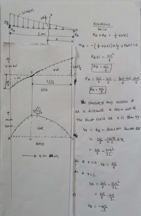
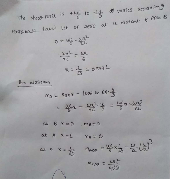
A cantilever beam supports the applied loads and moments as shown. (a) Calculate the support reactions....
 A cantilever beam supports the applied loads and moments as shown. (a) Calculate the support reactions. (b) Use the graphical method to construct the shear-force and bending moment diagrams for the beam. Also label the values of shear-force and bending=moment at all key points. 30 kN/m 25 kN 12 kN/m 80 kN.m х A В C D E F 1 m 3 m 1 m 1 m 1 m
4. For the beam and loading shown, draw the shear force and bending moment diagrams and...
 4. For the beam and loading shown, draw the shear force and bending moment diagrams and determine the maximum bending and shear force and their locations. 20 KN 40 KN B D 250 mm |--2.5 m- 3m-4-2 m 80 mm 5. For the beam and loading shown, draw the shear force and bending moment diagrams and determine the maximum bending and shear force and their locations. 50 KN
 Problem 1-3 Structures are shown in the figures 1)-3) 1) Draw all the FBDs for your calculation; 2) Determine the reactions at the support; 3) Draw shear and moment diagrams using the graphical method we discussed in today's class; lo o lb 5 1)
 Problem 1-5): Structures are shown in the figures 1) - 5) 1) Draw all the FBDs for your calculation; 2) Determine the reactions at the support; 3) Draw shear and moment diagrams using the graphical method we discussed in today's class. We were unable to transcribe this image
 Problem Determine the reactions and draw the shear and bending moment diagrams for the beams shown in Figs. P16.8-P16.14 by using the moment-distribution method 120 kN 120 kN 150 kN m--4 21 E 200 GPa 1- 500 (106 mm
 Need a good solution to check my work. Thanks.
2.1. For the following structures, calaculate support reactions and draw the deflection shape, bending moment, and shear force diagrams. All solutions must include Free Body Diagrams (FBDs). In case of structures with multiple members FBDs must be shown for every member. _ Hinge -Continous Beam 4m 4m 100 KN
Need a good solution to check my work. Thanks.
2.1. For the following structures, calaculate support reactions and draw the deflection shape, bending moment, and shear force diagrams. All solutions must include Free Body Diagrams (FBDs). In case of structures with multiple members FBDs must be shown for every member. _ Hinge -Continous Beam 4m 4m 100 KN
 Solve the following problems: (25 pts. each) Problem 1 Determine the support reactions then draw the shear and bending moment diagrams for the beam loaded as shown below P !!K LR4 Problem 2 Determine the support reactions then draw the shear and bending moment diagrams for the beam loaded as shown below 구K 4.5 ,81 7 Problem 3 Determine the support reactions then draw the shear and bending moment diagrams for the beam loaded as shown below. Ptok Problem 4...
 determine the support of the reactions for the loading shown.
Construct the shear and moment diagrams. find the locations at
which diagrams intersect the the x-axis if they do.
Problem 2 15 kN 4 kN/m 6m6m 1 kN/m
Problem 2 15 kN 4 kN/m 6m6m 1 kN/m
determine the support of the reactions for the loading shown.
Construct the shear and moment diagrams. find the locations at
which diagrams intersect the the x-axis if they do.
Problem 2 15 kN 4 kN/m 6m6m 1 kN/m
Problem 2 15 kN 4 kN/m 6m6m 1 kN/m
 Problem 4, (20%) For the case shown determine the displacements and the slopes at the nodes, the forces in each element, and the reactions. Also, draw the shear force and bending moment diagrams. 24 KN 4 m 4 m E = 70 GPa 1 = 2 x 10⁻⁴ m > k = 200 kN/m
 1) Determine the reactions at the supports for the structures shown. The support at A is a Roller and the support at B is a Pin. 2.0 k/ft M 10 k- 3.0 k/ft 12 ft 25 k- 25k-Pokift 15 ft B! 1 F20ft- 2) 2 3 k/ft A beam is supported at points A, C, and E, and is loaded as shown. The support at A is fixed. The supports at C and E are rollers. Hinge-B ce Dl Hinge...
 A cantilever beam supports the applied loads and moments as shown. (a) Calculate the support reactions. (b) Use the graphical method to construct the shear-force and bending moment diagrams for the beam. Also label the values of shear-force and bending=moment at all key points. 30 kN/m 25 kN 12 kN/m 80 kN.m х A В C D E F 1 m 3 m 1 m 1 m 1 m
 4. For the beam and loading shown, draw the shear force and bending moment diagrams and determine the maximum bending and shear force and their locations. 20 KN 40 KN B D 250 mm |--2.5 m- 3m-4-2 m 80 mm 5. For the beam and loading shown, draw the shear force and bending moment diagrams and determine the maximum bending and shear force and their locations. 50 KN
Most questions answered within 3 hours.
-
Write a program to solve the Josephus problem, with the following
modification:
Sample Input:
./a.out n...
asked 12 minutes ago -
At the start of a CD it is spinning at a rate of 525 rpm
(revolutions...
asked 48 minutes ago -
4. Without doing any calculations, predict whether the observed
∆T would increase, decrease or remain the...
asked 2 hours ago -
Based on the range, which of the following sets of scores has
the greatest variability? 3,...
asked 3 hours ago -
Ripples in a pond travel at a velocity of 3 m/s with one peak
passing a...
asked 3 hours ago -
A man stands on the roof of a building of height 13.0 mm and
throws a...
asked 3 hours ago -
The extent to which assets are financed by borrowed funds and
other liabilities is indicated by:...
asked 4 hours ago -
Explain in detail
Germany is the fifth largest economy
explain what goods and services Germany specializes...
asked 4 hours ago -
The density of platinum is 21.45 g/mL. If a cube of platinum
with a mass of...
asked 4 hours ago -
Accounts Receivable
Sales
A/R Posting
Extended Sales Invoice
Packing Slip
Compare invoice to packing slip 2...
asked 4 hours ago -
Michaella, age 23, is a full-time law student and is claimed by
her parents as a...
asked 4 hours ago -
Why are polymers not typically casted into products?
asked 4 hours ago