
Homework Answers
Add Answer to:
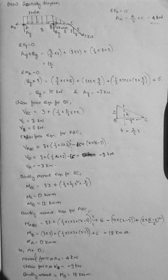
2 kN/m -6kNm 1. Calculate the internal bending moment, shear force, and normal force at Point...
Calculate the internal normal force, internal shear force, and internal bending moment at a location 0.75m...
 Calculate the internal normal force, internal shear force, and
internal bending moment at a location 0.75m to the right of the
fixed support A.
2. (20 points) Calculate the internal normal force, internal shear force, and internal bending moment at a location 0.75m to the right of the fixed support A 6 kN 30° 30° 1.5 m 4 kN 1.5 m1.5 m
Calculate the internal normal force, internal shear force, and
internal bending moment at a location 0.75m to the right of the
fixed support A.
2. (20 points) Calculate the internal normal force, internal shear force, and internal bending moment at a location 0.75m to the right of the fixed support A 6 kN 30° 30° 1.5 m 4 kN 1.5 m1.5 m
Q4) Find the interal normal force, shear force and bending moment at point is located at...
 Q4) Find the interal normal force, shear force and bending moment at point is located at distance 3ft from left side (20 points) Draw your section here 300 lb 200 lb/ Equation for finding normal force, N. Normal force, N Тb Equation for finding shear force, V. shear force, Ve Тb Equation for finding bending moment, M. Bending moment, M= ПЬНt
Given M-28 kN-m, and P-5 kN, find the internal bending moment at point C of the...
 Given M-28 kN-m, and P-5 kN, find the internal bending moment at point C of the beam in kN-m. 1.5m+← 1.5 m-+-1.5 m-+-1.5 m
Determine the internal normal force, shear force, and bending moment at point C in the beam.
 Determine the internal normal force, shear force, and bending moment at point C in the beam.
draw axial force, shear force and bending moment diagrams 2m 4'm 30 kN 2m 50 kN...
 draw axial force, shear force and bending moment
diagrams
2m 4'm 30 kN 2m 50 kN 4m A 3 m 1m -3m 1.5m
draw axial force, shear force and bending moment
diagrams
2m 4'm 30 kN 2m 50 kN 4m A 3 m 1m -3m 1.5m
#1) (65p.) Draw the Shear Force (V) and Bending Moment (M) diagrams of statically indeterminate beam...
 #1) (65p.) Draw the Shear Force (V) and Bending Moment (M) diagrams of statically indeterminate beam shown in figure using “Force Method". The (roller) support at "B" settles 35 mm. The moment of inertia is given by (1) for regions "AB", "BC" and "CD"; however it is equal to (21) for the region "DE". ("B" is the roller and "E" is the fixed type of support). [The flexural rigidity: El-40000 kNm"] 60 KN 10 kN/m B (1) (1) D (21)...
#1) (65p.) Draw the Shear Force (V) and Bending Moment (M) diagrams of statically indeterminate beam...
 #1) (65p.) Draw the Shear Force (V) and Bending Moment (M) diagrams of statically indeterminate beam shown in figure using “Force Method”. The (roller) support at “B” settles 35 mm. The moment of inertia is given by (I) for regions “AB”, “BC” and “CD”; however it is equal to (21) for the region “DE”. (“B” is the roller and “E” is the fixed type of support). [The flexural rigidity: EI=40000 kNm’] 60 KN 10 kN/m A B X (I) (I)...
Determine the internal normal force, shear force
 Determine the internal normal force, shear force, and moment at points C and D in the simply supported beam using method of sections. Point D is A located just to the left of the 5-kN force. Also, draw shear and moment diagrams using the graphical method.
2 kN Draw the shear-force and bending-moment diagrams for the beam loaded by the 2-kN force...
 2 kN Draw the shear-force and bending-moment diagrams for the beam loaded by the 2-kN force and the 1.6 kN-m couple. State the value of the bending moment at point B. HW22-2 1.6 kN.m 0.5m 0.5 m 0.5 m
 Calculate the internal normal force, internal shear force, and
internal bending moment at a location 0.75m to the right of the
fixed support A.
2. (20 points) Calculate the internal normal force, internal shear force, and internal bending moment at a location 0.75m to the right of the fixed support A 6 kN 30° 30° 1.5 m 4 kN 1.5 m1.5 m
Calculate the internal normal force, internal shear force, and
internal bending moment at a location 0.75m to the right of the
fixed support A.
2. (20 points) Calculate the internal normal force, internal shear force, and internal bending moment at a location 0.75m to the right of the fixed support A 6 kN 30° 30° 1.5 m 4 kN 1.5 m1.5 m
 Q4) Find the interal normal force, shear force and bending moment at point is located at distance 3ft from left side (20 points) Draw your section here 300 lb 200 lb/ Equation for finding normal force, N. Normal force, N Тb Equation for finding shear force, V. shear force, Ve Тb Equation for finding bending moment, M. Bending moment, M= ПЬНt
 Given M-28 kN-m, and P-5 kN, find the internal bending moment at point C of the beam in kN-m. 1.5m+← 1.5 m-+-1.5 m-+-1.5 m
 draw axial force, shear force and bending moment
diagrams
2m 4'm 30 kN 2m 50 kN 4m A 3 m 1m -3m 1.5m
draw axial force, shear force and bending moment
diagrams
2m 4'm 30 kN 2m 50 kN 4m A 3 m 1m -3m 1.5m
 #1) (65p.) Draw the Shear Force (V) and Bending Moment (M) diagrams of statically indeterminate beam shown in figure using “Force Method". The (roller) support at "B" settles 35 mm. The moment of inertia is given by (1) for regions "AB", "BC" and "CD"; however it is equal to (21) for the region "DE". ("B" is the roller and "E" is the fixed type of support). [The flexural rigidity: El-40000 kNm"] 60 KN 10 kN/m B (1) (1) D (21)...
 #1) (65p.) Draw the Shear Force (V) and Bending Moment (M) diagrams of statically indeterminate beam shown in figure using “Force Method”. The (roller) support at “B” settles 35 mm. The moment of inertia is given by (I) for regions “AB”, “BC” and “CD”; however it is equal to (21) for the region “DE”. (“B” is the roller and “E” is the fixed type of support). [The flexural rigidity: EI=40000 kNm’] 60 KN 10 kN/m A B X (I) (I)...
 #1) (65p.) Draw the Shear Force (V) and Bending Moment (M) diagrams of statically indeterminate beam shown in figure using “Force Method”. The (roller) support at “B” settles 35 mm. The moment of inertia is given by (I) for regions “AB”, “BC” and “CD”; however it is equal to (21) for the region “DE”. (“B” is the roller and “E” is the fixed type of support). [The flexural rigidity: EI=40000 kNm’] 60 KN 10 kN/m A B X (I) (I)...
 2 kN Draw the shear-force and bending-moment diagrams for the beam loaded by the 2-kN force and the 1.6 kN-m couple. State the value of the bending moment at point B. HW22-2 1.6 kN.m 0.5m 0.5 m 0.5 m
Most questions answered within 3 hours.
-
3) What are the typical social structures in a global city?
asked 1 hour ago -
Luther Corporation
Consolidated Balance Sheet
December 31, 2019 and 2018 (in $ millions)
Assets
2019
2018...
asked 1 hour ago -
(Expected rate of return and risk) Carter Inc. is evaluating a
security. Calculate the investment’s expected...
asked 4 hours ago -
What specific indicators can point to lack of progress for
African Americans in American society?
asked 5 hours ago -
1-The Electrons in a beam are moving at 2.7×10⁸ m/s in an
electric field of 15000...
asked 5 hours ago -
A gas tank is a vertical cylinder. It has a radius of 1m, a
height of...
asked 6 hours ago -
Accent Software faces the following conditions. All of these
support Accent’s use of a market-penetration pricing...
asked 7 hours ago -
A mathematically inclined friend emails you the following
instructions: "Meet me in the cafeteria the first...
asked 7 hours ago -
A monopoly sells in two countries . The demand curves in the two
countries are p1...
asked 8 hours ago -
A .15kg rubber ball is bounced off a wall. Before hitting the
wall, the ball moves...
asked 8 hours ago -
A manufacturing company preparing to build a new plant is
considering three potential locations for it....
asked 8 hours ago -
B. If compound Y has approximately the same values of solubility
in toluene as compound X,...
asked 9 hours ago