
use mesh nodal or branch analysis
Homework Answers

Add Answer to:
use mesh nodal or branch analysis
MW2201 Ri measured = Vabs R24 Rc w - 1...
5. Use mesh analysis to find the currents through every branch in the circuit below Assume...
 5. Use mesh analysis to find the currents through every branch in the circuit below Assume Ri = 10 Ω, R,-5 Ω, R,-4D, R,-1 Ω, Vi = 5 V, and ½ = 2 V.(Textbook Problem 3.33) Ri R2 Rs Vi R4
Use measured resistance values and node analysis to calculate the node voltages. Use measured resistance values...
 Use measured resistance values and node analysis to calculate
the node voltages.
Use measured resistance values and mesh analysis to calculate
the mesh currents.
Show that the calculated values agree with the measured values
and explain any discrepancies between measured and calculated
values.
Introduction: In this pre-lab we will look at node voltages, mesh currents and bridge circuits. Bridge Circuits are used to make precision measurements, and in this lab -- -0 V2 will look at a DC Bridge Circuit...
Use measured resistance values and node analysis to calculate
the node voltages.
Use measured resistance values and mesh analysis to calculate
the mesh currents.
Show that the calculated values agree with the measured values
and explain any discrepancies between measured and calculated
values.
Introduction: In this pre-lab we will look at node voltages, mesh currents and bridge circuits. Bridge Circuits are used to make precision measurements, and in this lab -- -0 V2 will look at a DC Bridge Circuit...
3-1 Use nodal analysis to find v, in the circuit shown in Fig. 3-6 if element...
 3-1 Use nodal analysis to find v, in the circuit shown in Fig. 3-6 if element A is: (a) a 2-A current source, arrow pointing right; (b) an 8-92 resistor; (c) a 10-V voltage source, the positive reference on the right. ns:- 17 A 2Ω Fig. 3-6 See Drill Probs. 3-1 and 3-2.
kennesaw.view.usgedu uit Analysis I XLS Group H3 Surme Bb Collaborate Sessions ats > Labs > Lab...
 kennesaw.view.usgedu uit Analysis I XLS Group H3 Surme Bb Collaborate Sessions ats > Labs > Lab 5 > Lab-5 2101-03 - Collabot < Task 1. Thévenin Analysis a. Analytical Calculations: Determine the resulting Thévenin equivalent for circuit 1 by calculating the Voc (using Voltage Divider Rule or Nodal Analysis), Isc (using Mesh Analysis) and Rth (using Delta-Wye conversion with voltage source deactivated). You must show detailed step-by-step calculations with relevant circuit diagrams. Given: R1 = 1 k-2, R2 = 2.2...
RESISTOR VALUES: R1=1k, R2=2k, R3=3k, R4=3.9k, R5=5.1k, R6=6.2k, R7=6.8K NUMBERS: 2, 4, & 5 1 Short AB, as shown in...
 RESISTOR VALUES: R1=1k, R2=2k, R3=3k, R4=3.9k, R5=5.1k, R6=6.2k,
R7=6.8K
NUMBERS: 2, 4, & 5
1 Short AB, as shown in Figure 3 - 2 (a). Use mesh analysis to calculate the voltage across each resistor and the current through AB, IAB 2. Leave AB open, as shown in Figure 3 - 2 (b). Use nodal analysis to calculate the voltage across each resistor as well as the voltage across AB, VAB 3. Find Thevenin's and Norton's Equivalent using the results...
RESISTOR VALUES: R1=1k, R2=2k, R3=3k, R4=3.9k, R5=5.1k, R6=6.2k,
R7=6.8K
NUMBERS: 2, 4, & 5
1 Short AB, as shown in Figure 3 - 2 (a). Use mesh analysis to calculate the voltage across each resistor and the current through AB, IAB 2. Leave AB open, as shown in Figure 3 - 2 (b). Use nodal analysis to calculate the voltage across each resistor as well as the voltage across AB, VAB 3. Find Thevenin's and Norton's Equivalent using the results...
Course and Section cto EXPERIMENT ac series-Parallel Sinusoidal Circuits OBJECTIVES 1. Measure th...
 Course and Section cto EXPERIMENT ac series-Parallel Sinusoidal Circuits OBJECTIVES 1. Measure the currents of series-parallel R-L and R-C networks using sensing resistors 2. Demonstrate the Pythagorean relationship between the currents of the networks. 3. Measure the phase angles associated with the currents of the networks. 4. Calculate the input impedance of a parallel network using measured values EQUIPMENT REQUIRED Instruments Resistors 1-10-Q, 470-Ω, l-kM (14.W) Inductors 1-10-mH Capacitors 1-0.02-pF I-DMM 1--Oscilloscope 1-Audio oscillator or function generator 1--Frequency counter (if...
Electronics1. It's a multiple choices question. use the formula sheet if needed (the last picture). Statement:...
 Electronics1. It's a multiple choices question. use the formula
sheet if needed (the last picture).
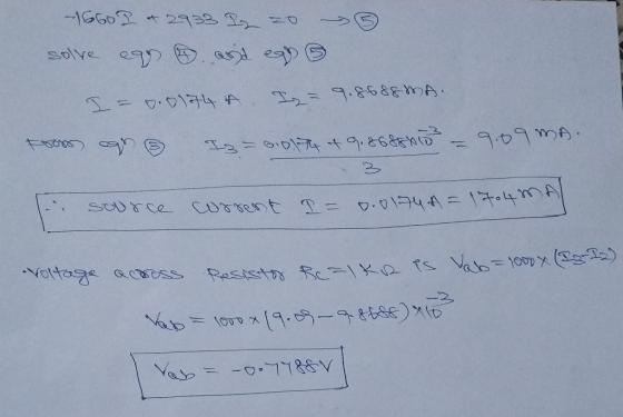
Statement: Sketching relevant output (Vele) characteristics decide on Q-point coordinates and DC load-line details: That is, determine DC operating conditions of the NPN-BJT/Si circuit of Fig. 7 (denoting the type Circuit C2). Assume the following: Voc = 18 volt; Ve=0.7; R = 1.5 k: Re2 = 33 k; Vc = 9.5 volt; Inc = 9.5 and, B = 100 Voc Re lac Ro Ne I...
Electronics1. It's a multiple choices question. use the formula
sheet if needed (the last picture).
Statement: Sketching relevant output (Vele) characteristics decide on Q-point coordinates and DC load-line details: That is, determine DC operating conditions of the NPN-BJT/Si circuit of Fig. 7 (denoting the type Circuit C2). Assume the following: Voc = 18 volt; Ve=0.7; R = 1.5 k: Re2 = 33 k; Vc = 9.5 volt; Inc = 9.5 and, B = 100 Voc Re lac Ro Ne I...
1. Why can the DSO only measure node voltages when the Function Generator is the power supply in ...
 1. Why can the DSO only measure node voltages when the Function Generator is the power supply in a circuit (unless it is using a current probe)? 2. Consider Figure 1. According to the calculations in the lab handout, if Z-1kΩ +/6914, then the phase difference (фи-фі) between u(t) and i (t) is 34.6". a. If this v(t) and i(t) were displayed on a DSO (v(t) being a node voltage and using a current probe for i(t) as shown in...
 5. Use mesh analysis to find the currents through every branch in the circuit below Assume Ri = 10 Ω, R,-5 Ω, R,-4D, R,-1 Ω, Vi = 5 V, and ½ = 2 V.(Textbook Problem 3.33) Ri R2 Rs Vi R4
 Use measured resistance values and node analysis to calculate
the node voltages.
Use measured resistance values and mesh analysis to calculate
the mesh currents.
Show that the calculated values agree with the measured values
and explain any discrepancies between measured and calculated
values.
Introduction: In this pre-lab we will look at node voltages, mesh currents and bridge circuits. Bridge Circuits are used to make precision measurements, and in this lab -- -0 V2 will look at a DC Bridge Circuit...
Use measured resistance values and node analysis to calculate
the node voltages.
Use measured resistance values and mesh analysis to calculate
the mesh currents.
Show that the calculated values agree with the measured values
and explain any discrepancies between measured and calculated
values.
Introduction: In this pre-lab we will look at node voltages, mesh currents and bridge circuits. Bridge Circuits are used to make precision measurements, and in this lab -- -0 V2 will look at a DC Bridge Circuit...
 3-1 Use nodal analysis to find v, in the circuit shown in Fig. 3-6 if element A is: (a) a 2-A current source, arrow pointing right; (b) an 8-92 resistor; (c) a 10-V voltage source, the positive reference on the right. ns:- 17 A 2Ω Fig. 3-6 See Drill Probs. 3-1 and 3-2.
 kennesaw.view.usgedu uit Analysis I XLS Group H3 Surme Bb Collaborate Sessions ats > Labs > Lab 5 > Lab-5 2101-03 - Collabot < Task 1. Thévenin Analysis a. Analytical Calculations: Determine the resulting Thévenin equivalent for circuit 1 by calculating the Voc (using Voltage Divider Rule or Nodal Analysis), Isc (using Mesh Analysis) and Rth (using Delta-Wye conversion with voltage source deactivated). You must show detailed step-by-step calculations with relevant circuit diagrams. Given: R1 = 1 k-2, R2 = 2.2...
 RESISTOR VALUES: R1=1k, R2=2k, R3=3k, R4=3.9k, R5=5.1k, R6=6.2k,
R7=6.8K
NUMBERS: 2, 4, & 5
1 Short AB, as shown in Figure 3 - 2 (a). Use mesh analysis to calculate the voltage across each resistor and the current through AB, IAB 2. Leave AB open, as shown in Figure 3 - 2 (b). Use nodal analysis to calculate the voltage across each resistor as well as the voltage across AB, VAB 3. Find Thevenin's and Norton's Equivalent using the results...
RESISTOR VALUES: R1=1k, R2=2k, R3=3k, R4=3.9k, R5=5.1k, R6=6.2k,
R7=6.8K
NUMBERS: 2, 4, & 5
1 Short AB, as shown in Figure 3 - 2 (a). Use mesh analysis to calculate the voltage across each resistor and the current through AB, IAB 2. Leave AB open, as shown in Figure 3 - 2 (b). Use nodal analysis to calculate the voltage across each resistor as well as the voltage across AB, VAB 3. Find Thevenin's and Norton's Equivalent using the results...
 Course and Section cto EXPERIMENT ac series-Parallel Sinusoidal Circuits OBJECTIVES 1. Measure the currents of series-parallel R-L and R-C networks using sensing resistors 2. Demonstrate the Pythagorean relationship between the currents of the networks. 3. Measure the phase angles associated with the currents of the networks. 4. Calculate the input impedance of a parallel network using measured values EQUIPMENT REQUIRED Instruments Resistors 1-10-Q, 470-Ω, l-kM (14.W) Inductors 1-10-mH Capacitors 1-0.02-pF I-DMM 1--Oscilloscope 1-Audio oscillator or function generator 1--Frequency counter (if...
 Electronics1. It's a multiple choices question. use the formula
sheet if needed (the last picture).
Statement: Sketching relevant output (Vele) characteristics decide on Q-point coordinates and DC load-line details: That is, determine DC operating conditions of the NPN-BJT/Si circuit of Fig. 7 (denoting the type Circuit C2). Assume the following: Voc = 18 volt; Ve=0.7; R = 1.5 k: Re2 = 33 k; Vc = 9.5 volt; Inc = 9.5 and, B = 100 Voc Re lac Ro Ne I...
Electronics1. It's a multiple choices question. use the formula
sheet if needed (the last picture).
Statement: Sketching relevant output (Vele) characteristics decide on Q-point coordinates and DC load-line details: That is, determine DC operating conditions of the NPN-BJT/Si circuit of Fig. 7 (denoting the type Circuit C2). Assume the following: Voc = 18 volt; Ve=0.7; R = 1.5 k: Re2 = 33 k; Vc = 9.5 volt; Inc = 9.5 and, B = 100 Voc Re lac Ro Ne I...
 1. Why can the DSO only measure node voltages when the Function Generator is the power supply in a circuit (unless it is using a current probe)? 2. Consider Figure 1. According to the calculations in the lab handout, if Z-1kΩ +/6914, then the phase difference (фи-фі) between u(t) and i (t) is 34.6". a. If this v(t) and i(t) were displayed on a DSO (v(t) being a node voltage and using a current probe for i(t) as shown in...
Most questions answered within 3 hours.
-
Please answer true or false. Words
cannot be changed or added in to make it true...
asked 54 minutes ago -
An empty test tube weighs 15.923 grams. Then,
MgCl2•6H2O is added into the test tube. After...
asked 56 minutes ago -
(a) A piston at 6.1 atm contains a gas that occupies a volume of
3.5 L....
asked 55 minutes ago -
Assume memory access is 10 units of time and disk access is
10000 units of time....
asked 1 hour ago -
1. Are all good samples random?
2. Magazines often report surveys giving statistics such as “63%...
asked 1 hour ago -
Under all the various types of market structures, firms
must eventually earn some economic profits for...
asked 1 hour ago -
Consider the following fitness regime for a single locus trait
with two co-dominant alleles: w11 =...
asked 1 hour ago -
A large cable company reports the following.
80% of its customers subscribe to its cable TV...
asked 1 hour ago -
Please answer the question in brief.
Discuss the role of ERP in organizations. Are ERP tools...
asked 1 hour ago -
Discuss the pros and cons of collaborative software such
as SameTime. Does it increase productivity? What...
asked 1 hour ago -
Buying your in-laws a gift because it’s expected is
due to the ____________ motive of gift-giving....
asked 1 hour ago -
Calculate the expected value, the variance, and the standard
deviation of the given random variable X....
asked 2 hours ago