
please help me answer 100% correct answer. very important hand writing must be clear and easy to read
Homework Answers


Add Answer to:
please help me answer 100% correct answer. very important hand
writing must be clear and easy...
Please help me answer 100 correctly i am sending this question for 3rd time but i...
 Please help me answer 100 correctly i am sending this question
for 3rd time but i didnt get proper answer please help me answer
with formula and explanation . please make sure hand writting can
read easy. if can please type ur answer. please help me.
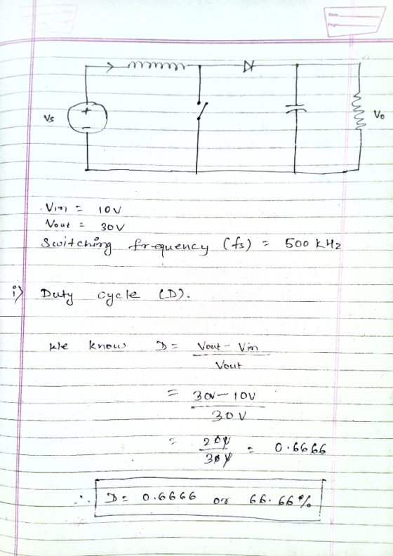
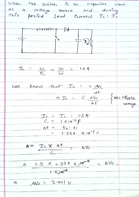
b) The capacitance, inductance and load resistance of a Boost step-up dc-to-dc converter are 1.0μF, 10μΗ and 20.0Ω respectively. It is used to converter 10V dc input to 30V dc output. The switching frequency...
Please help me answer 100 correctly i am sending this question
for 3rd time but i didnt get proper answer please help me answer
with formula and explanation . please make sure hand writting can
read easy. if can please type ur answer. please help me.
b) The capacitance, inductance and load resistance of a Boost step-up dc-to-dc converter are 1.0μF, 10μΗ and 20.0Ω respectively. It is used to converter 10V dc input to 30V dc output. The switching frequency...
Question 1 (25 marks) a) A full wave rectifier has 40V peak secondary voltage, 2,000uF capacitor...
 Question 1 (25 marks) a) A full wave rectifier has 40V peak secondary voltage, 2,000uF capacitor and 1022 load. You may take the line frequency as 50Hz and voltage drop across a diode as 0.7V. i. Calculate the peak dc voltage (VA). (2 marks) ii. Calculate the dc load voltage (Vdcloed). (4 marks) iii. Calculate the ripple voltage (AVLoad). (4 marks) b) The capacitance, inductance and load resistance of a Buck step-down dc-to-dc converter are 1.0uF, 10uH and 20.022 respectively....
Design a DC-DC boost converter, shown below, that converts an unregulated supply of 12.0 Vak into a load voltage of...
 Design a DC-DC boost converter, shown below, that converts an unregulated supply of 12.0 Vak into a load voltage of 30.0 Ve and load current of 0.25 A. The switching frequency of the transistor is 100 kHz. The transistor has an on-resistance of 0.15 Ω and the diode drops 0.7 V when it is conducting. The voltage ripple (Av) is taken as 20 mVpp The circuit has 80% conversion efficiency. Find the DC input-current (Iden), duty-cycle (D), inductance (L), power-dissipation...
Q5. 5.a. Sketch the circuit arrangement of a DC-DC boost (step up) converter, clearly labelling each...
 Q5. 5.a. Sketch the circuit arrangement of a DC-DC boost (step up) converter, clearly labelling each circuit element [4 тarks] [Refer to lecture notes] Sketch all significant operating waveforms for this converter for continuous conduction conditions over two switching periods, in particular showing 5.b. the voltage across the main switching device and the boost diode. [2 marks the voltage across the inductor [3 тarks] the current flowing through the inductor [3 marks [Refer to lecture notes] 5.c. The DC-DC boost...
Please answer 2 and 1. Assignment No.6 10mH, C-20μF, an 1. A boost converter as the...
 Please answer 2 and 1.
Assignment No.6 10mH, C-20μF, an 1. A boost converter as the following parameters: V,-20V, L Find the current spec of the inductor for continuous current mode (Max an Min current) -20 2. Switching frequency is 50 KHz and conduction duty cycle is 0.6 a. b. Calculate the output voltage and the ripple voltage An array has been formed with three modules in a string and two strings in parallel. The overall characteristic of the array...
Please answer 2 and 1.
Assignment No.6 10mH, C-20μF, an 1. A boost converter as the following parameters: V,-20V, L Find the current spec of the inductor for continuous current mode (Max an Min current) -20 2. Switching frequency is 50 KHz and conduction duty cycle is 0.6 a. b. Calculate the output voltage and the ripple voltage An array has been formed with three modules in a string and two strings in parallel. The overall characteristic of the array...
18 marks load with a power of 25.6 W.The cy f is 40kHz. sign a buck-boost converter to produce an output voltage of 16V a put voltage ripple must not exceed 1%. The dc input voltage is 24V. Th e swit...
 18 marks load with a power of 25.6 W.The cy f is 40kHz. sign a buck-boost converter to produce an output voltage of 16V a put voltage ripple must not exceed 1%. The dc input voltage is 24V. Th e switching frequen 121 a) the duty ratio b) Find the size of the inductor so that the maximum inductor current c) the size of the capacitor d) Assume L=1 00μH and the switching frequency fis variable. 141 121 Lma 10A...
2. Renewable energy system requires a boost converter with input voltage variation of 18 V to 42 ...
 2. Renewable energy system requires a boost converter with input voltage variation of 18 V to 42 V (de) and gives output of 120 V at 0.6 kW. For the converter the switching frequency is set at 50 kHz. a) Find the operating duty cycle range for each switch of the converter0 marks b) 196 What is the inductor value which should keep inductor current variation below under all input voltages [30 marks] c) Find the capacitor value which should...
A PV array with terminal voltage around 48 V under standard conditions is connected to a step-up dc-dc converter to supply a load at 120 V, 5 A. The input inductance is 8 mH with an internal resistanc...
A PV array with terminal voltage around 48 V under standard conditions is connected to a step-up dc-dc converter to supply a load at 120 V, 5 A. The input inductance is 8 mH with an internal resistance of 0.2 ohms, and the switching frequency is 5 kHz. Assuming ideal circuit components, calculate the duty ratio (k) and average input current (I1). Evaluate the maximum peak-to-peak input current ripple for the converter. If this current is limited to 2% of...
Buck Converter Question Q3. A Buck converter is used to produce a regulated 10V, 5A DC...
 Buck Converter Question
Q3. A Buck converter is used to produce a regulated 10V, 5A DC power supply from a variable DC source with an nominal input voltage of Vin = 20V±5V. The Buck converter switches at 250kHz, and operates entirely in the continuous conduction mode. The output filter capacitance is C1.0uF 3.a. Draw the circuit topology for the Buck converter. Ensure that your circuit includes the input DC source, the output load resistance, the switching devices (i.e. MOSFET and...
Buck Converter Question
Q3. A Buck converter is used to produce a regulated 10V, 5A DC power supply from a variable DC source with an nominal input voltage of Vin = 20V±5V. The Buck converter switches at 250kHz, and operates entirely in the continuous conduction mode. The output filter capacitance is C1.0uF 3.a. Draw the circuit topology for the Buck converter. Ensure that your circuit includes the input DC source, the output load resistance, the switching devices (i.e. MOSFET and...
Design a boost converter power stage to the following specification: Input voltage Output voltage: Output voltage...
 Design a boost converter power stage to the following specification: Input voltage Output voltage: Output voltage ripple:max 20mV Load power: Switching frequency: 15kHz 110-125V 300V 1.5kW Calculate: (i) Maximum duty cycle (ii) Minimum duty cycle (iii) Average diode current (iv) Assuming the Rds(on) of the MOSFET is 0.01 Ω, and the diode forward voltage is 0.8V, calculate the approximate efficiency of the circuit. 2. A switching power supply shown in the circuit below has its switch driven by a signal...
 Please help me answer 100 correctly i am sending this question
for 3rd time but i didnt get proper answer please help me answer
with formula and explanation . please make sure hand writting can
read easy. if can please type ur answer. please help me.
b) The capacitance, inductance and load resistance of a Boost step-up dc-to-dc converter are 1.0μF, 10μΗ and 20.0Ω respectively. It is used to converter 10V dc input to 30V dc output. The switching frequency...
Please help me answer 100 correctly i am sending this question
for 3rd time but i didnt get proper answer please help me answer
with formula and explanation . please make sure hand writting can
read easy. if can please type ur answer. please help me.
b) The capacitance, inductance and load resistance of a Boost step-up dc-to-dc converter are 1.0μF, 10μΗ and 20.0Ω respectively. It is used to converter 10V dc input to 30V dc output. The switching frequency...
 Question 1 (25 marks) a) A full wave rectifier has 40V peak secondary voltage, 2,000uF capacitor and 1022 load. You may take the line frequency as 50Hz and voltage drop across a diode as 0.7V. i. Calculate the peak dc voltage (VA). (2 marks) ii. Calculate the dc load voltage (Vdcloed). (4 marks) iii. Calculate the ripple voltage (AVLoad). (4 marks) b) The capacitance, inductance and load resistance of a Buck step-down dc-to-dc converter are 1.0uF, 10uH and 20.022 respectively....
 Design a DC-DC boost converter, shown below, that converts an unregulated supply of 12.0 Vak into a load voltage of 30.0 Ve and load current of 0.25 A. The switching frequency of the transistor is 100 kHz. The transistor has an on-resistance of 0.15 Ω and the diode drops 0.7 V when it is conducting. The voltage ripple (Av) is taken as 20 mVpp The circuit has 80% conversion efficiency. Find the DC input-current (Iden), duty-cycle (D), inductance (L), power-dissipation...
 Q5. 5.a. Sketch the circuit arrangement of a DC-DC boost (step up) converter, clearly labelling each circuit element [4 тarks] [Refer to lecture notes] Sketch all significant operating waveforms for this converter for continuous conduction conditions over two switching periods, in particular showing 5.b. the voltage across the main switching device and the boost diode. [2 marks the voltage across the inductor [3 тarks] the current flowing through the inductor [3 marks [Refer to lecture notes] 5.c. The DC-DC boost...
 Please answer 2 and 1.
Assignment No.6 10mH, C-20μF, an 1. A boost converter as the following parameters: V,-20V, L Find the current spec of the inductor for continuous current mode (Max an Min current) -20 2. Switching frequency is 50 KHz and conduction duty cycle is 0.6 a. b. Calculate the output voltage and the ripple voltage An array has been formed with three modules in a string and two strings in parallel. The overall characteristic of the array...
Please answer 2 and 1.
Assignment No.6 10mH, C-20μF, an 1. A boost converter as the following parameters: V,-20V, L Find the current spec of the inductor for continuous current mode (Max an Min current) -20 2. Switching frequency is 50 KHz and conduction duty cycle is 0.6 a. b. Calculate the output voltage and the ripple voltage An array has been formed with three modules in a string and two strings in parallel. The overall characteristic of the array...
 18 marks load with a power of 25.6 W.The cy f is 40kHz. sign a buck-boost converter to produce an output voltage of 16V a put voltage ripple must not exceed 1%. The dc input voltage is 24V. Th e switching frequen 121 a) the duty ratio b) Find the size of the inductor so that the maximum inductor current c) the size of the capacitor d) Assume L=1 00μH and the switching frequency fis variable. 141 121 Lma 10A...
 2. Renewable energy system requires a boost converter with input voltage variation of 18 V to 42 V (de) and gives output of 120 V at 0.6 kW. For the converter the switching frequency is set at 50 kHz. a) Find the operating duty cycle range for each switch of the converter0 marks b) 196 What is the inductor value which should keep inductor current variation below under all input voltages [30 marks] c) Find the capacitor value which should...
 Buck Converter Question
Q3. A Buck converter is used to produce a regulated 10V, 5A DC power supply from a variable DC source with an nominal input voltage of Vin = 20V±5V. The Buck converter switches at 250kHz, and operates entirely in the continuous conduction mode. The output filter capacitance is C1.0uF 3.a. Draw the circuit topology for the Buck converter. Ensure that your circuit includes the input DC source, the output load resistance, the switching devices (i.e. MOSFET and...
Buck Converter Question
Q3. A Buck converter is used to produce a regulated 10V, 5A DC power supply from a variable DC source with an nominal input voltage of Vin = 20V±5V. The Buck converter switches at 250kHz, and operates entirely in the continuous conduction mode. The output filter capacitance is C1.0uF 3.a. Draw the circuit topology for the Buck converter. Ensure that your circuit includes the input DC source, the output load resistance, the switching devices (i.e. MOSFET and...
 Design a boost converter power stage to the following specification: Input voltage Output voltage: Output voltage ripple:max 20mV Load power: Switching frequency: 15kHz 110-125V 300V 1.5kW Calculate: (i) Maximum duty cycle (ii) Minimum duty cycle (iii) Average diode current (iv) Assuming the Rds(on) of the MOSFET is 0.01 Ω, and the diode forward voltage is 0.8V, calculate the approximate efficiency of the circuit. 2. A switching power supply shown in the circuit below has its switch driven by a signal...
Most questions answered within 3 hours.
-
(1) Write the net ionic equation for the reaction that occurs
when equal volumes of 0.191...
asked 23 seconds from now -
Q1
Two of your friends each received the results of their
first midterm exam this term....
asked 10 minutes ago -
A 0.500-kg object, suspended from an ideal spring of spring
constant 30.2 N/m, is oscillating vertically....
asked 8 minutes ago -
Please help and show work. I keep getting the wrong answers for
these problems
1. Cell...
asked 5 minutes ago -
If there is a SNP in the read with respect to the
reference genome, how would a...
asked 8 minutes ago -
Early black-and-white television sets used an electron beam to
draw a picture on the screen. The...
asked 10 minutes ago -
What is the standard error of M (denoted as
σM ) ?
Options:
The mean of...
asked 34 minutes ago -
Explain the role of n, the sample size, in determining the size
of a generated confidence...
asked 23 minutes ago -
Kelsey Drums, Inc., is a well-established supplier of fine
percussion instruments to orchestras all over the...
asked 37 minutes ago -
In a criminal case, the state must not prove its case beyond a
reasonable doubt. T/F
asked 42 minutes ago -
5.6 dm^3 of gaseous HCl (as measured in normal conditions) is
dissolved in 100 cm^3 of...
asked 51 minutes ago -
The hammer throw is a track-and-field event in which a 7.2-kg
ball (the ''hammer''), starting from...
asked 1 hour ago