
Homework Answers

Add Answer to:
3.4. Consider a finite element with shape functions N(E) and N2(E) used to interpolate the displacement...
Problem 2. Consider a finite element with shape functions N1 (ξ) and N2Ģ) used to interpolate...
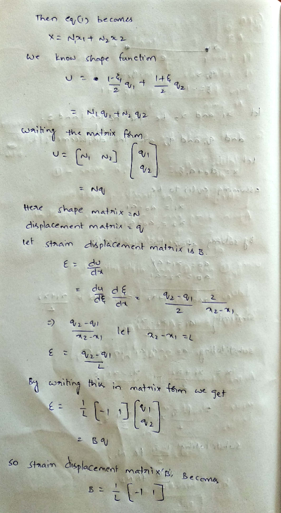
 Problem 2. Consider a finite element with shape functions N1 (ξ) and N2Ģ) used to interpolate the displacement field within the element shown below. Derive an expression for the strain-displacement matrix B where strain E-Bq, in terms of N1 and N2. (Do not assume any specific form for N and N2.) (Note: q[1 21.) 72--
Problem 1 Consider the bar shown below with a cross-sectional area A, 1.2 m2, and Young's...
 Problem 1 Consider the bar shown below with a cross-sectional area A, 1.2 m2, and Young's modulus E-200 X 109 Pa. Ifq,-0.02 m and q,-0.025 m determine the following (by hand calculation) (a) the displacement at point P., (b) the strain E and stress σ (e) the element stiffness matrix, and (d) the strain energy in the element 91 *p 20 m x,-15 m x,-23 m Problem 2. Consider a finite element with shape functions N1) and N2(Š) used to...
Finite element method A) Total potential energy of a spring system Write the expression for the...
 Finite element method
A) Total potential energy of a spring system Write the expression for the total potential energy of the spring system below 11 ki 43 1lg ii) Specify the boundary conditions B) Shape function and its properties i) Write the expression for the shape function matrix N- [N(C) N,(o)] and strain- !-[ dN displacement matrix B=|ー1 for a typical two-node linear trusbar element shown dx below N, (x) = N, (x) x,-x, x2-XI x1 Element 1 Node 2...
Finite element method
A) Total potential energy of a spring system Write the expression for the total potential energy of the spring system below 11 ki 43 1lg ii) Specify the boundary conditions B) Shape function and its properties i) Write the expression for the shape function matrix N- [N(C) N,(o)] and strain- !-[ dN displacement matrix B=|ー1 for a typical two-node linear trusbar element shown dx below N, (x) = N, (x) x,-x, x2-XI x1 Element 1 Node 2...
Section 1: Finite Element Derivation and Validation In this section of the report you will develop your own Finite Elem...
 Section 1: Finite Element Derivation and Validation In this section of the report you will develop your own Finite Element method for 1-dimensional axial loading. The governing equation for displacement, u is Poisson's Equation: อั1 where E is the modulus of elasticity, A(a) is the cross-sectional area as a function of length, and q(x) is the loading distribution as a function of length. The weak form of this equation with 0 1. Starting from the weak form of the governing...
Q.2 (a) (Continued) (11) For an isoparametric element, explain the relationship between shape functions, the geometry...
 Q.2 (a) (Continued) (11) For an isoparametric element, explain the relationship between shape functions, the geometry of the element and the shape the loaded element will deform to. (3 marks) (iv) Describe the relationship between structural equilibrium and the minimum potential energy state. (3 marks) (b) Imman F FIGURE Q2b: 3 Springs (0) Derive an expression for the Total Potential Energy of the structure shown above in Q2b. (5 marks) (1) Apply the minimum potential energy method to derive the...
Q2 (a) (0) Explain what is meant by interpolation in the Finite Element Method and why...
 Q2 (a) (0) Explain what is meant by interpolation in the Finite Element Method and why it is used (3 marks) What is a shape function? (3 marks) PLEASE TURN OVER 16363,16367 Page 2 of 3 0.2 (a) (Continued) (iii) For an isoparametric element, explain the relationship between shape functions, the geometry of the element and the shape the loaded element will deform to. (3 marks) (iv) Describe the relationship between structural equilibrium and the minimum potential energy state. (3...
X=0 x = 1/2 x= L u U2 Uz (a) Trial solution for a 1-D quadratic...
 X=0 x = 1/2 x= L u U2 Uz (a) Trial solution for a 1-D quadratic elastic bar element can be written as follows: ū(x) = [N]{u} where, [N] = [N1 N2 N3] and {u} u2 13 1 and Ni L2 L2 [N] and {u} are known as interpolation function matrix and nodal displacement, respectively. (272 – 3L + L´), N= = (22- La), Ns = 12 (2=– LE) Derive the expression for element stiffness matrix, (Kelem) and element force...
)Given a 4-node element in x-y plane as shown here: Node X 3 3 1 8 a) Using the shape functions in u-v plane, determine an expression for mapped points from u-v to x-y, i.e. x- x(u, v) and y -y(u...
 )Given a 4-node element in x-y plane as shown here: Node X 3 3 1 8 a) Using the shape functions in u-v plane, determine an expression for mapped points from u-v to x-y, i.e. x- x(u, v) and y -y(u, v), for points within the 4-node element in u-v plane. Then, determine value of x and y for a point with (u, v)-(0.3,0.3). (10 points) b) Determine the value of Jacobian matrix, [J], and its determinant for such mapping...
Consider a cylindrical capacitor like that shown in Fig. 24.6. Let d = rb − ra...
 Consider a cylindrical capacitor like that shown in Fig. 24.6. Let d = rb − ra be the spacing between the inner and outer conductors. (a) Let the radii of the two conductors be only slightly different, so that d << ra. Show that the result derived in Example 24.4 (Section 24.1) for the capacitance of a cylindrical capacitor then reduces to Eq. (24.2), the equation for the capacitance of a parallel-plate capacitor, with A being the surface area of...
 Problem 2. Consider a finite element with shape functions N1 (ξ) and N2Ģ) used to interpolate the displacement field within the element shown below. Derive an expression for the strain-displacement matrix B where strain E-Bq, in terms of N1 and N2. (Do not assume any specific form for N and N2.) (Note: q[1 21.) 72--
 Problem 1 Consider the bar shown below with a cross-sectional area A, 1.2 m2, and Young's modulus E-200 X 109 Pa. Ifq,-0.02 m and q,-0.025 m determine the following (by hand calculation) (a) the displacement at point P., (b) the strain E and stress σ (e) the element stiffness matrix, and (d) the strain energy in the element 91 *p 20 m x,-15 m x,-23 m Problem 2. Consider a finite element with shape functions N1) and N2(Š) used to...
 Finite element method
A) Total potential energy of a spring system Write the expression for the total potential energy of the spring system below 11 ki 43 1lg ii) Specify the boundary conditions B) Shape function and its properties i) Write the expression for the shape function matrix N- [N(C) N,(o)] and strain- !-[ dN displacement matrix B=|ー1 for a typical two-node linear trusbar element shown dx below N, (x) = N, (x) x,-x, x2-XI x1 Element 1 Node 2...
Finite element method
A) Total potential energy of a spring system Write the expression for the total potential energy of the spring system below 11 ki 43 1lg ii) Specify the boundary conditions B) Shape function and its properties i) Write the expression for the shape function matrix N- [N(C) N,(o)] and strain- !-[ dN displacement matrix B=|ー1 for a typical two-node linear trusbar element shown dx below N, (x) = N, (x) x,-x, x2-XI x1 Element 1 Node 2...
 Section 1: Finite Element Derivation and Validation In this section of the report you will develop your own Finite Element method for 1-dimensional axial loading. The governing equation for displacement, u is Poisson's Equation: อั1 where E is the modulus of elasticity, A(a) is the cross-sectional area as a function of length, and q(x) is the loading distribution as a function of length. The weak form of this equation with 0 1. Starting from the weak form of the governing...
 Section 1: Finite Element Derivation and Validation In this section of the report you will develop your own Finite Element method for 1-dimensional axial loading. The governing equation for displacement, u is Poisson's Equation: อั1 where E is the modulus of elasticity, A(a) is the cross-sectional area as a function of length, and q(x) is the loading distribution as a function of length. The weak form of this equation with 0 1. Starting from the weak form of the governing...
 Q.2 (a) (Continued) (11) For an isoparametric element, explain the relationship between shape functions, the geometry of the element and the shape the loaded element will deform to. (3 marks) (iv) Describe the relationship between structural equilibrium and the minimum potential energy state. (3 marks) (b) Imman F FIGURE Q2b: 3 Springs (0) Derive an expression for the Total Potential Energy of the structure shown above in Q2b. (5 marks) (1) Apply the minimum potential energy method to derive the...
 Q2 (a) (0) Explain what is meant by interpolation in the Finite Element Method and why it is used (3 marks) What is a shape function? (3 marks) PLEASE TURN OVER 16363,16367 Page 2 of 3 0.2 (a) (Continued) (iii) For an isoparametric element, explain the relationship between shape functions, the geometry of the element and the shape the loaded element will deform to. (3 marks) (iv) Describe the relationship between structural equilibrium and the minimum potential energy state. (3...
 X=0 x = 1/2 x= L u U2 Uz (a) Trial solution for a 1-D quadratic elastic bar element can be written as follows: ū(x) = [N]{u} where, [N] = [N1 N2 N3] and {u} u2 13 1 and Ni L2 L2 [N] and {u} are known as interpolation function matrix and nodal displacement, respectively. (272 – 3L + L´), N= = (22- La), Ns = 12 (2=– LE) Derive the expression for element stiffness matrix, (Kelem) and element force...
 )Given a 4-node element in x-y plane as shown here: Node X 3 3 1 8 a) Using the shape functions in u-v plane, determine an expression for mapped points from u-v to x-y, i.e. x- x(u, v) and y -y(u, v), for points within the 4-node element in u-v plane. Then, determine value of x and y for a point with (u, v)-(0.3,0.3). (10 points) b) Determine the value of Jacobian matrix, [J], and its determinant for such mapping...
 Consider a cylindrical capacitor like that shown in Fig. 24.6. Let d = rb − ra be the spacing between the inner and outer conductors. (a) Let the radii of the two conductors be only slightly different, so that d << ra. Show that the result derived in Example 24.4 (Section 24.1) for the capacitance of a cylindrical capacitor then reduces to Eq. (24.2), the equation for the capacitance of a parallel-plate capacitor, with A being the surface area of...
Most questions answered within 3 hours.
-
2. KopyKat is a firm that specializes in printing business cards
using the latest laser technology....
asked 8 minutes ago -
What type of stock pays dividends in arrears?
A.
Nonminus−cumulative
preferred stock
B.
Cumulative preferred stock...
asked 6 minutes ago -
Discuss what issues you see as needing to be addressed in an
organization in order to...
asked 8 minutes ago -
Why does varying input frequency to a buck converter affect the
magnitude of the output voltage...
asked 11 minutes ago -
Given the following reduction half-reactions:
Fe3+(aq)+e−→Fe2+(aq)
E∘red=+0.77V
S2O2−6(aq)+4H+(aq)+2e−→2H2SO3(aq)
E∘red=+0.60V
N2O(g)+2H+(aq)+2e−→N2(g)+H2O(l)
E∘red=−1.77V
VO+2(aq)+2H+(aq)+e−→VO2+(aq)+H2O(l)
E∘red=+1.00V
Write balanced chemica
asked 12 minutes ago -
Consider a random variable X with PDF given by f(x)=1/10 for x =
0, 1, 2,...,9....
asked 10 minutes ago -
This is QA Tester's task
What was the most heinous bug that you let slip through?...
asked 24 minutes ago -
What is the chemical equation (with states) for this
reaction in balanced and unbalanced form?
In...
asked 27 minutes ago -
In engineering and product design, it is important to consider
the weights of people so that...
asked 32 minutes ago -
The first-order decomposition of N2O5 at 328 K has a rate
constant of 1.70 × 10⁻³...
asked 34 minutes ago -
Do you believe that some things that fall into the category of
“pseudoscience” are worth believing...
asked 57 minutes ago -
A 0.100-kg, 59.6-cm-long uniform bar has a small 0.070-kg mass
glued to its left end and...
asked 48 minutes ago