


Homework Answers

Add Answer to:
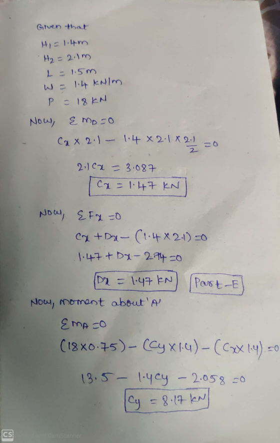
Learning Goal: To solve for the support reactions of a frame. The frame shown in (Figure...
Learning Goal: To analyze a rod assembly in three-dimensional space and determine the support reactions by...
 Learning Goal: To analyze a rod assembly in three-dimensional space and determine the support reactions by using the equations of equilibrium for a rigid body. The rod assembly shown has smooth journal bearings at A, B, and C. The forces Fi = 500 N, F = 440 N, F3 = 480 N and FA = 975 N are applied as shown in the figure. The geometry of the rod assembly is given as a = 0.800 m, b=0.550 m ,...
Learning Goal: To apply the equations of motion to a system that involves rotation about a...
 Learning Goal: To apply the equations of motion to a system that involves rotation about a fixed axis and to use this information to determine key characteristics The slender rod AB shown has a mass of m 51.0 kg and is being supported by a rope and pulley system stationed at C. Starting from rest in the position shown), the rope and pulley system tug on the rod causing it to rotate about A The torque applied to the pulley...
Part A - Angular Acceleration of the Rod Learning Goal: To apply the equations of motion...
 Part A - Angular Acceleration of the Rod Learning Goal: To apply the equations of motion to a system that involves rotation about a fixed axis and to use this information to determine key characteristics. The slender rod AB shown has a mass of m = 71.0 kg and is being supported by a rope and pulley system stationed at C. Starting from rest in the position shown), the rope and pulley system tug on the rod causing it to...
Learning Goal: To apply the equations of motion to a system that involves rotation about a...
 Learning Goal: To apply the equations of motion to a system that involves rotation about a fixed axis and to use this information to determine key characteristics. The slender rod AB shown has a mass of m=61.0 kg and is being supported by a rope and pulley system stationed at C. Starting from rest (in the position shown), the rope and pulley system tug on the rod causing it to rotate about A. The torque applied to the pulley is...
Learning Goal: To apply the equations of motion to a system that involves rotation about a...
 Learning Goal: To apply the equations of motion to a system that involves rotation about a fixed axis and to use this information to determine key characteristics. The slender rod AB shown has a mass of m = 51.0 kg and is being supported by a rope and pulley system stationed at C. Starting from rest (in the position shown), the rope and pulley system tug on the rod causing it to rotate about A. The torque applied to the...
Leaming Goal: To determine the shear stresses at specific locations in a beam due to an...
 Leaming Goal: To determine the shear stresses at specific locations in a beam due to an external loading. Beam ABC is subjected to the loading shown, where PB = 40.0 kN. The measurement corresponding to the half-length of the beam is a = 2.50 m. For the cross section shown, b = 50.0 mm, c= 125.0 mm, d = 125.0 mm, and e = 65.0 mm Point Dis located at the centroid of the cross section and point E is...
Learning Goal: Part A - Force with a known deflection To solve for forces in statically...
 Learning Goal: Part A - Force with a known deflection To solve for forces in statically indeterminate bars with axial loads. When the number of reaction forces is greater than the number of equilibrium equations, the system is slatically indeterminate. Solving for the reactions requires some additional equations. These additional equations come from considering compatibility relationships (.e., continuity of displacements and relationships between displacements and loads). For an axially loaded member, the compatibility relationship for the deflections can be written...
I Review Learning Goal: To use the principle of linear impulse to determine the change in...
 I Review Learning Goal: To use the principle of linear impulse to determine the change in velocity of a box subject to multiple forces Part A What is the magnitude of the normal force between the box and the ground? Express your answer to three significant figures with appropriate units. The block shown in (Figure 1) has mass m = 40 kg and is subjected to forces Fi = 300 N at an angle 0 = 20 ° below the...
Solve for E please Review (MR).= -2.88 kN-m Submit Previous Answers Learning Goal: To determine the...
 Solve for E please
Review (MR).= -2.88 kN-m Submit Previous Answers Learning Goal: To determine the location and direction of a single equivalent force for a coplanar force system. The frame shown in (Figure 1) has dimensions H = 3.1 m and L = 0.9 m and is subjected to the forces P1 = 4.5 kN, P2 = 8.5 kN, and P3 = 11.5 KN. Force P3 is applied Ay = 0.4 m down from the top. ✓ Correct Part...
Solve for E please
Review (MR).= -2.88 kN-m Submit Previous Answers Learning Goal: To determine the location and direction of a single equivalent force for a coplanar force system. The frame shown in (Figure 1) has dimensions H = 3.1 m and L = 0.9 m and is subjected to the forces P1 = 4.5 kN, P2 = 8.5 kN, and P3 = 11.5 KN. Force P3 is applied Ay = 0.4 m down from the top. ✓ Correct Part...
Learning Goal: Part A = 10 m ? To calculate the normal and tangential components of...
 Learning Goal: Part A = 10 m ? To calculate the normal and tangential components of the acceleration of an object along a given path. A particle is traveling along the path y(x) = 0.3z?, as shown in (Figure 1), where y is in meters when is in meters. When I 10 m, the particle's velocity is v = 17 m/s and the magnitude of its acceleration is a = 1.6 m/s . Determine the normal and tangential components of...
 Learning Goal: To analyze a rod assembly in three-dimensional space and determine the support reactions by using the equations of equilibrium for a rigid body. The rod assembly shown has smooth journal bearings at A, B, and C. The forces Fi = 500 N, F = 440 N, F3 = 480 N and FA = 975 N are applied as shown in the figure. The geometry of the rod assembly is given as a = 0.800 m, b=0.550 m ,...
 Learning Goal: To apply the equations of motion to a system that involves rotation about a fixed axis and to use this information to determine key characteristics The slender rod AB shown has a mass of m 51.0 kg and is being supported by a rope and pulley system stationed at C. Starting from rest in the position shown), the rope and pulley system tug on the rod causing it to rotate about A The torque applied to the pulley...
 Part A - Angular Acceleration of the Rod Learning Goal: To apply the equations of motion to a system that involves rotation about a fixed axis and to use this information to determine key characteristics. The slender rod AB shown has a mass of m = 71.0 kg and is being supported by a rope and pulley system stationed at C. Starting from rest in the position shown), the rope and pulley system tug on the rod causing it to...
 Learning Goal: To apply the equations of motion to a system that involves rotation about a fixed axis and to use this information to determine key characteristics. The slender rod AB shown has a mass of m=61.0 kg and is being supported by a rope and pulley system stationed at C. Starting from rest (in the position shown), the rope and pulley system tug on the rod causing it to rotate about A. The torque applied to the pulley is...
 Learning Goal: To apply the equations of motion to a system that involves rotation about a fixed axis and to use this information to determine key characteristics. The slender rod AB shown has a mass of m = 51.0 kg and is being supported by a rope and pulley system stationed at C. Starting from rest (in the position shown), the rope and pulley system tug on the rod causing it to rotate about A. The torque applied to the...
 Leaming Goal: To determine the shear stresses at specific locations in a beam due to an external loading. Beam ABC is subjected to the loading shown, where PB = 40.0 kN. The measurement corresponding to the half-length of the beam is a = 2.50 m. For the cross section shown, b = 50.0 mm, c= 125.0 mm, d = 125.0 mm, and e = 65.0 mm Point Dis located at the centroid of the cross section and point E is...
 Learning Goal: Part A - Force with a known deflection To solve for forces in statically indeterminate bars with axial loads. When the number of reaction forces is greater than the number of equilibrium equations, the system is slatically indeterminate. Solving for the reactions requires some additional equations. These additional equations come from considering compatibility relationships (.e., continuity of displacements and relationships between displacements and loads). For an axially loaded member, the compatibility relationship for the deflections can be written...
 I Review Learning Goal: To use the principle of linear impulse to determine the change in velocity of a box subject to multiple forces Part A What is the magnitude of the normal force between the box and the ground? Express your answer to three significant figures with appropriate units. The block shown in (Figure 1) has mass m = 40 kg and is subjected to forces Fi = 300 N at an angle 0 = 20 ° below the...
 Solve for E please
Review (MR).= -2.88 kN-m Submit Previous Answers Learning Goal: To determine the location and direction of a single equivalent force for a coplanar force system. The frame shown in (Figure 1) has dimensions H = 3.1 m and L = 0.9 m and is subjected to the forces P1 = 4.5 kN, P2 = 8.5 kN, and P3 = 11.5 KN. Force P3 is applied Ay = 0.4 m down from the top. ✓ Correct Part...
Solve for E please
Review (MR).= -2.88 kN-m Submit Previous Answers Learning Goal: To determine the location and direction of a single equivalent force for a coplanar force system. The frame shown in (Figure 1) has dimensions H = 3.1 m and L = 0.9 m and is subjected to the forces P1 = 4.5 kN, P2 = 8.5 kN, and P3 = 11.5 KN. Force P3 is applied Ay = 0.4 m down from the top. ✓ Correct Part...
 Learning Goal: Part A = 10 m ? To calculate the normal and tangential components of the acceleration of an object along a given path. A particle is traveling along the path y(x) = 0.3z?, as shown in (Figure 1), where y is in meters when is in meters. When I 10 m, the particle's velocity is v = 17 m/s and the magnitude of its acceleration is a = 1.6 m/s . Determine the normal and tangential components of...
Most questions answered within 3 hours.
-
Homologous Recombination Lecture
Molecular Biology
The ability for yeast and E. coli to do
homologous recombination...
asked 7 minutes ago -
A single pass heat exchanger is used to cool milk from 65 C to
20 C...
asked 7 minutes ago -
A water pistol aimed horizontally projects a stream of water
with an initial speed of 7.20...
asked 11 minutes ago -
Language: Python
Function name : findwaldo
Parameters : string
Returns: int
Description: Write a recursive function...
asked 30 minutes ago -
1) A loan of RM 10,000 at a flat rate of 10% per annum was
repaid...
asked 36 minutes ago -
Suppose you have been following a particular airline stock for
many years. You are interested in...
asked 42 minutes ago -
Describe the organic pasta: Is it a normal/inferior
good? Is it a necessity/luxury? Does it have...
asked 44 minutes ago -
Are Republicans just as likely as Democrats to display the
American flag in front of their...
asked 53 minutes ago -
Select the true statement below.
nitrogen dioxide is a stronger potential oxidizing agent than
dinitrogen monoxide...
asked 57 minutes ago -
What’s the probability of getting a sequence of 1,2,3,4,5,6 if
we roll a dice six times?
asked 58 minutes ago -
Ibarra Corporation uses the FIFO method in its process costing
system. The first processing department, the...
asked 59 minutes ago -
Multiple Choice Question:
Jennifer Jones, a 38-year-old employee at a metal fabricating
plant, was injured in...
asked 1 hour ago