
Homework Answers


Add Answer to:
P1 P1 P1 The cage system shown in the figure, EB “Force Method” by taking the...
P1 050 A B Solve the system with the “Force Method” by taking the A support...
 P1 050 A B Solve the system with the “Force Method” by taking the A support reaction of the frame system shown in the figure unknown. Draw the M-V diagrams. (A is mobile, C is built-in support.) (P1 load is right in the middle of the bar) * EI 2ΕΙ Ly1 |c LX1 LX2 LY1 P1 P2 + 10,9m 9,4m 6,6m 9kN 3,1kN LX1 LX1 * * * El: Constant
user Kajal J. ı dont want to your solution ı want to different solution P1 P1...
 user Kajal J. ı dont want to your solution ı want to different
solution
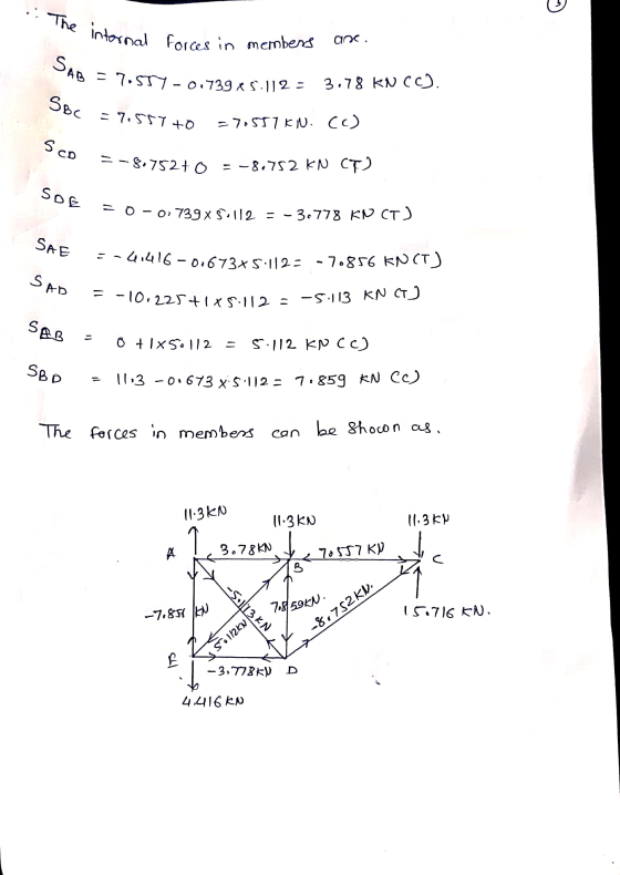
P1 P1 P1 A 00 Ly1 E D Lx2 LX1 * Use the EB is unknown solve this system by Force Method and find internel forces El: Constant Lxl: 4.4 lx2: 8.8 lyl: 11.7 m pl: 3,3 kn
user Kajal J. ı dont want to your solution ı want to different
solution
P1 P1 P1 A 00 Ly1 E D Lx2 LX1 * Use the EB is unknown solve this system by Force Method and find internel forces El: Constant Lxl: 4.4 lx2: 8.8 lyl: 11.7 m pl: 3,3 kn
P2 B 5Р. 2) The frame system shown in the figure is “Angle Method”. M-V diagrams...
 P2 B 5Р. 2) The frame system shown in the figure is “Angle Method”. M-V diagrams Draw. P1 as external torque for this question will be used and its unit will be taken as kN-m. (A and E are built-in bearings.) please make the solution readable с 2E1 ΕΙ Ly1/2 P1 EI ΕΙ Ly1/2 LX1(m) LX2(m) LY1(m)P1(kN) P2(Kn/m) 5,5 2,2 7,6 5,3 4,6 E Lx2
Using MATLAB PLease For scaffolding system shown, assume P1-50 lbf and P2-20 lbf. Perform force and momentum equilibrium balances for each bar to find 4 equations. Then show how to set them up as one...
 Using MATLAB PLease
For scaffolding system shown, assume P1-50 lbf and P2-20 lbf. Perform force and momentum equilibrium balances for each bar to find 4 equations. Then show how to set them up as one system of linear equations ( Ax-b)and solve in MATLAB to determine tension forces T.Ty.TC and To. Hint: write ΣFy-Oand ΣΜ-Ofor each bar to find the equations. Bar 1
For scaffolding system shown, assume P1-50 lbf and P2-20 lbf. Perform force and momentum equilibrium balances for...
Using MATLAB PLease
For scaffolding system shown, assume P1-50 lbf and P2-20 lbf. Perform force and momentum equilibrium balances for each bar to find 4 equations. Then show how to set them up as one system of linear equations ( Ax-b)and solve in MATLAB to determine tension forces T.Ty.TC and To. Hint: write ΣFy-Oand ΣΜ-Ofor each bar to find the equations. Bar 1
For scaffolding system shown, assume P1-50 lbf and P2-20 lbf. Perform force and momentum equilibrium balances for...
Figure 1 shows a mechanical system suspended between a fixed ceiling and a moving base. Taking...
 Figure 1 shows a mechanical system suspended between a fixed ceiling and a moving base. Taking the base motion zin(t) as the input to this system, please answer the following: Fixed Zin() Moving base Figure 1: Problem 1: One-mass moving base system. (a) (2 points) Draw a free-body diagram for mass m clearly showing your sign conventions for the co- ordinates and external forces. (Assume the spring is pre-compressed under the weight mg, e.g. the z and Zin coordinates are...
Use the Force Method to derive the slope-deflection relationship given in class (and provided in step...
 Use the Force Method to derive
the slope-deflection relationship given in class (and provided in
step 7 below) for Mab and Mba (as defined in the figure below) as
functions of Theta_A. E and I are constant.
Assignment #11 Due: 11/26/2018 a 12pm Draw a free-body diagram for each problem clearly showing loads and reactions Summarize in one location all of your final answers together, with directions of displacements showrn You must show your work in order to receive full...
Use the Force Method to derive
the slope-deflection relationship given in class (and provided in
step 7 below) for Mab and Mba (as defined in the figure below) as
functions of Theta_A. E and I are constant.
Assignment #11 Due: 11/26/2018 a 12pm Draw a free-body diagram for each problem clearly showing loads and reactions Summarize in one location all of your final answers together, with directions of displacements showrn You must show your work in order to receive full...
1. The block shown in the figure has a mass of 612 Kg. The static coefficient...
 1. The block shown in the figure has a mass of 612 Kg. The static coefficient of friction between the block and the supporting surface is 0.33 while the kinetic coefficient of friction is 0.26. Ignore the size of the block. Force P is parallel to the incline while the 1000N force is vertical. a) If P = 2000 N, the shown block is (circle the correct answer) (5 points) a) in equilibrium b) moving up the incline c) is...
Analyse the beam shown in Figure 4 using the stiffiness method. Node D is fixed and...
 Analyse the beam shown in Figure 4 using the stiffiness method. Node D is fixed and node 2 and 3 are rollers. A uniform distributed load of 1 kN/m is acting on member 1 . And a load of 10 kN is acting at the middle of member2. EI is constant for all members a) Identify the force vector of the structure; [4 marks] b) Identify the displacement vector of the structure; [2 marks] c) Determine the stiffness matrices of...
A support beam of a conveyor system supports the loads shown in the figure...
 A support beam of a conveyor system supports the loads shown in the figure. The support points are points A and C. The 20kN load in B and the 10 kN load in D must be applied suddenly many thousands of times. A 50mm diameter circular steel bar was proposed to make the beam. A torque of 10 kN-m was added to the original design at point D. The steel is AISI 4140, determine the factor of safety by the...
3. Analyze the system shown in Figure 3. (40 points) Copyright © McGraw-Hill Education. Permission required...
 3. Analyze the system shown in Figure 3. (40 points) Copyright © McGraw-Hill Education. Permission required for reproduction or display 300 lb/ft - 4 ft 2 ft2 ft 300 lb Figure 2: Simply supported beam subject to a distributed load and a concentrated force Note: the Concentrated force at Point D induces a force on the beam and a moment on the beam both at Points C 3. Solve for the internal forces and moments in each region using integration...
 P1 050 A B Solve the system with the “Force Method” by taking the A support reaction of the frame system shown in the figure unknown. Draw the M-V diagrams. (A is mobile, C is built-in support.) (P1 load is right in the middle of the bar) * EI 2ΕΙ Ly1 |c LX1 LX2 LY1 P1 P2 + 10,9m 9,4m 6,6m 9kN 3,1kN LX1 LX1 * * * El: Constant
 user Kajal J. ı dont want to your solution ı want to different
solution
P1 P1 P1 A 00 Ly1 E D Lx2 LX1 * Use the EB is unknown solve this system by Force Method and find internel forces El: Constant Lxl: 4.4 lx2: 8.8 lyl: 11.7 m pl: 3,3 kn
user Kajal J. ı dont want to your solution ı want to different
solution
P1 P1 P1 A 00 Ly1 E D Lx2 LX1 * Use the EB is unknown solve this system by Force Method and find internel forces El: Constant Lxl: 4.4 lx2: 8.8 lyl: 11.7 m pl: 3,3 kn
 P2 B 5Р. 2) The frame system shown in the figure is “Angle Method”. M-V diagrams Draw. P1 as external torque for this question will be used and its unit will be taken as kN-m. (A and E are built-in bearings.) please make the solution readable с 2E1 ΕΙ Ly1/2 P1 EI ΕΙ Ly1/2 LX1(m) LX2(m) LY1(m)P1(kN) P2(Kn/m) 5,5 2,2 7,6 5,3 4,6 E Lx2
 Using MATLAB PLease
For scaffolding system shown, assume P1-50 lbf and P2-20 lbf. Perform force and momentum equilibrium balances for each bar to find 4 equations. Then show how to set them up as one system of linear equations ( Ax-b)and solve in MATLAB to determine tension forces T.Ty.TC and To. Hint: write ΣFy-Oand ΣΜ-Ofor each bar to find the equations. Bar 1
For scaffolding system shown, assume P1-50 lbf and P2-20 lbf. Perform force and momentum equilibrium balances for...
Using MATLAB PLease
For scaffolding system shown, assume P1-50 lbf and P2-20 lbf. Perform force and momentum equilibrium balances for each bar to find 4 equations. Then show how to set them up as one system of linear equations ( Ax-b)and solve in MATLAB to determine tension forces T.Ty.TC and To. Hint: write ΣFy-Oand ΣΜ-Ofor each bar to find the equations. Bar 1
For scaffolding system shown, assume P1-50 lbf and P2-20 lbf. Perform force and momentum equilibrium balances for...
 Figure 1 shows a mechanical system suspended between a fixed ceiling and a moving base. Taking the base motion zin(t) as the input to this system, please answer the following: Fixed Zin() Moving base Figure 1: Problem 1: One-mass moving base system. (a) (2 points) Draw a free-body diagram for mass m clearly showing your sign conventions for the co- ordinates and external forces. (Assume the spring is pre-compressed under the weight mg, e.g. the z and Zin coordinates are...
 Use the Force Method to derive
the slope-deflection relationship given in class (and provided in
step 7 below) for Mab and Mba (as defined in the figure below) as
functions of Theta_A. E and I are constant.
Assignment #11 Due: 11/26/2018 a 12pm Draw a free-body diagram for each problem clearly showing loads and reactions Summarize in one location all of your final answers together, with directions of displacements showrn You must show your work in order to receive full...
Use the Force Method to derive
the slope-deflection relationship given in class (and provided in
step 7 below) for Mab and Mba (as defined in the figure below) as
functions of Theta_A. E and I are constant.
Assignment #11 Due: 11/26/2018 a 12pm Draw a free-body diagram for each problem clearly showing loads and reactions Summarize in one location all of your final answers together, with directions of displacements showrn You must show your work in order to receive full...
 1. The block shown in the figure has a mass of 612 Kg. The static coefficient of friction between the block and the supporting surface is 0.33 while the kinetic coefficient of friction is 0.26. Ignore the size of the block. Force P is parallel to the incline while the 1000N force is vertical. a) If P = 2000 N, the shown block is (circle the correct answer) (5 points) a) in equilibrium b) moving up the incline c) is...
 Analyse the beam shown in Figure 4 using the stiffiness method. Node D is fixed and node 2 and 3 are rollers. A uniform distributed load of 1 kN/m is acting on member 1 . And a load of 10 kN is acting at the middle of member2. EI is constant for all members a) Identify the force vector of the structure; [4 marks] b) Identify the displacement vector of the structure; [2 marks] c) Determine the stiffness matrices of...
 3. Analyze the system shown in Figure 3. (40 points) Copyright © McGraw-Hill Education. Permission required for reproduction or display 300 lb/ft - 4 ft 2 ft2 ft 300 lb Figure 2: Simply supported beam subject to a distributed load and a concentrated force Note: the Concentrated force at Point D induces a force on the beam and a moment on the beam both at Points C 3. Solve for the internal forces and moments in each region using integration...
Most questions answered within 3 hours.
-
Water has significant IMF, which result in many of its unique
properties—high boiling point relative to...
asked 18 minutes ago -
I need help with an executive summary for Adidas Items to be
included are a discription...
asked 11 minutes ago -
19. Most progressive reform activists were white
and a. upper class. b. lower class. c. wokring...
asked 13 minutes ago -
If X is a binomial random variable with n = 8
and p = 0.2, the...
asked 24 minutes ago -
Seasonal or cyclical variation in a time-series model…
---exhibits irregular
variation that can be accounted for...
asked 25 minutes ago -
Please use Barney's VRIO framework of analysis to evaluate a
firm's competencies. Please choose a specific...
asked 38 minutes ago -
Where would you expect to have diabetes contributing to the most
DALYs in 2035, according to...
asked 39 minutes ago -
1.) Major league baseball salaries averaged $1.5 million with a
standard deviation of $1 million in...
asked 48 minutes ago -
A hedge fund is holding a three-year,
$10 million face value 6 percent annual coupon bond...
asked 59 minutes ago -
The focal length of a makeup (concave) mirror is 0.48 m. What
magnification does this mirror...
asked 1 hour ago -
TRUE/FALSE
Long-lived assets that are tangible in nature, used in the
operations of the business, and...
asked 1 hour ago -
A dragon biologist is setting up an experimental population of
1000 individuals. In dragons, pointy crests...
asked 1 hour ago