Solve the question A-1,2,3 & B please.


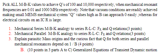
Below is the reference materials.

Homework Answers


Add Answer to:
Solve the question A-1,2,3 & B please.
Below is the reference materials.
II. Second Order...
Can someone please clearly write out their process for finding V out while using Laplace Transform. YOU CAN IGNORE parts...
 Can someone please clearly write out their process for finding V
out while using Laplace Transform. YOU CAN IGNORE parts e and f
2. Parallel LCR Circuit: For the parallel circuit below, a. Find the real output voltage v(t). b. Find the real currents in the components; iL(t), iR(t) and ic(t) c. What is the resonant frequency wo? d. Derive an expression for the Q of the circuit (without the current source, of course) e. Make a log-log plot of...
Can someone please clearly write out their process for finding V
out while using Laplace Transform. YOU CAN IGNORE parts e and f
2. Parallel LCR Circuit: For the parallel circuit below, a. Find the real output voltage v(t). b. Find the real currents in the components; iL(t), iR(t) and ic(t) c. What is the resonant frequency wo? d. Derive an expression for the Q of the circuit (without the current source, of course) e. Make a log-log plot of...
2. (14 marks total) This question deals with the series RLC circuit discussed in the classroom...
 2. (14 marks total) This question deals with the series RLC circuit discussed in the classroom and in the labs. Assume that the voltage source is arbitrary and there is a non-zero charge, g(0), on the capacitor at time t 0 when a switch is closed to start current flow. For this question assume variable R, L and C values. (a) Write down the differential equation that describes the charge on the capacitor as a function of time. (2 marks)...
Please help with the following question correctly for thumbs up! 5. + -11 points SerPSE 10...
 Please help with the following question correctly for thumbs
up!
5. + -11 points SerPSE 10 32.7.P.026. A series RLC circuit has components with the following values: L = 18.0 mH, C = 80.0 nF, R = 30.0 2, and AVmax = 100 V, with Av = AV may sin wt. (a) Find the resonant frequency of the circuit. kHz (b) Find the amplitude of the current at the resonant frequency. (c) Find the Q of the circuit. (d) Find...
Please help with the following question correctly for thumbs
up!
5. + -11 points SerPSE 10 32.7.P.026. A series RLC circuit has components with the following values: L = 18.0 mH, C = 80.0 nF, R = 30.0 2, and AVmax = 100 V, with Av = AV may sin wt. (a) Find the resonant frequency of the circuit. kHz (b) Find the amplitude of the current at the resonant frequency. (c) Find the Q of the circuit. (d) Find...
Design a second-order Butterworth low-pass filter to satisfy the specifications a. The dc gain is...
 Design a second-order Butterworth low-pass filter to satisfy the specifications a. The dc gain is unity (zero dB); b. The gain is no smaller than -1 dB for frequencies between 0 and 2,000 Hz; and c. The gain is no larger than -40 dB for frequencies larger than 40 kHz. Determine a circuit realization as a series RLC low-pass filter. Pick reasonable values of R, L, and C.
Design a second-order Butterworth low-pass filter to satisfy the specifications a. The...
Design a second-order Butterworth low-pass filter to satisfy the specifications a. The dc gain is unity (zero dB); b. The gain is no smaller than -1 dB for frequencies between 0 and 2,000 Hz; and c. The gain is no larger than -40 dB for frequencies larger than 40 kHz. Determine a circuit realization as a series RLC low-pass filter. Pick reasonable values of R, L, and C.
Design a second-order Butterworth low-pass filter to satisfy the specifications a. The...
Three radio stations broadcast at three different carrier frequencies: TIL Ulaucasts at three different carrier frequencies:...
 Three radio stations broadcast at three different carrier
frequencies:
TIL Ulaucasts at three different carrier frequencies: 700 kHz, 1000 kHz, and 1400 Hz The antenna at the radio receiver front-end receives the voltage signals from all three stations, so the input to the radio receiver (tuner) will be the sum of these signals. You are asked to design a parallel resonant RLC circuit with a quality factor of 15 to be used as a tuner to receive only the broadcast...
Three radio stations broadcast at three different carrier
frequencies:
TIL Ulaucasts at three different carrier frequencies: 700 kHz, 1000 kHz, and 1400 Hz The antenna at the radio receiver front-end receives the voltage signals from all three stations, so the input to the radio receiver (tuner) will be the sum of these signals. You are asked to design a parallel resonant RLC circuit with a quality factor of 15 to be used as a tuner to receive only the broadcast...
please solve question 5 and 6 and give detailed description if possible . here is the...
 please solve question 5 and 6
and give detailed description if possible .
here is the figure
3.3.3. PRELAB WORK For the circuit shown in Figure 18. (a), assume L 2mH, and C 5nF 1. Calculate fo and the value of R to give a circuit of Q of 5. 2. Calculate the values of f1. f2 and B using Equations (34), (35), (29), and (30) 3, 4. For the same circuit assume L 2mH, C 5nF and R 1002....
please solve question 5 and 6
and give detailed description if possible .
here is the figure
3.3.3. PRELAB WORK For the circuit shown in Figure 18. (a), assume L 2mH, and C 5nF 1. Calculate fo and the value of R to give a circuit of Q of 5. 2. Calculate the values of f1. f2 and B using Equations (34), (35), (29), and (30) 3, 4. For the same circuit assume L 2mH, C 5nF and R 1002....
HI GUYS CAN YOU HELP ME SOLVE THIS QUESTION ASAP PLS AND THANKS!! QUESTION 6 ONLY,...
 HI GUYS CAN YOU HELP ME SOLVE THIS QUESTION ASAP PLS AND
THANKS!! QUESTION 6 ONLY, THE 15 MARK QUESTION. CAN YOU CALCULATE
THE THEOREATICAL VALUES WITH THESE 3 VALUES: 10HZ, 1KHZ, 10KHZ. AND
USING THIS VALUES. R = 1000Ω,C = 1µF, L = 0.23mh. not the L=44
thanks.
Exercise 2 [60 marks] RLC Circuit as a Low-pass Filter L 0000 in out Figure 2. RLC circuit 2 10 marks] Derive the second order input-output model (differential equation) for the...
HI GUYS CAN YOU HELP ME SOLVE THIS QUESTION ASAP PLS AND
THANKS!! QUESTION 6 ONLY, THE 15 MARK QUESTION. CAN YOU CALCULATE
THE THEOREATICAL VALUES WITH THESE 3 VALUES: 10HZ, 1KHZ, 10KHZ. AND
USING THIS VALUES. R = 1000Ω,C = 1µF, L = 0.23mh. not the L=44
thanks.
Exercise 2 [60 marks] RLC Circuit as a Low-pass Filter L 0000 in out Figure 2. RLC circuit 2 10 marks] Derive the second order input-output model (differential equation) for the...
4. Consider a series RLC circuit driven by a voltage source with capacitor voltage as output. Ass...
 4. Consider a series RLC circuit driven by a voltage source with capacitor voltage as output. Assume the following parameter values: R 20n, L ;: 1 mH, C : 5μF a. b. c. d. Write down the transfer function of the system Choose a sample time for the system Find the pulse transfer function (use MATLAB 'c2d' command) Find the range of K for stability for the closed-loop sampled-data system
4. Consider a series RLC circuit driven by a voltage...
4. Consider a series RLC circuit driven by a voltage source with capacitor voltage as output. Assume the following parameter values: R 20n, L ;: 1 mH, C : 5μF a. b. c. d. Write down the transfer function of the system Choose a sample time for the system Find the pulse transfer function (use MATLAB 'c2d' command) Find the range of K for stability for the closed-loop sampled-data system
4. Consider a series RLC circuit driven by a voltage...
2. LRC series circuit. [10 pts.] Consider an LRC series circuit driven by an ac voltage source Vi...
 2. LRC series circuit. [10 pts.] Consider an LRC series circuit driven by an ac voltage source Vin Vo cos(wt). (a) Derive an expression for the real ac current in the circuit in terms of L, R, C, and a. (b) Determine the resonant frequency f, and angular frequency w, by direct differentiation of the current amplitude from part (a). Compare your result to LC (c) Determine the Q factor of this circuit in terms of L, R, and C....
Please help me solve this urgently [15%] input voltage is given by 1. what is th...
 Please help me solve this urgently
[15%] input voltage is given by 1. what is th e transfer function and the output voltage for the circuit shown below? The Vin(1)-10+8cos(5Oxt-90") +4cos(100t +60°). 40 mH Problem 1 2. [1596] Design an R-L-C parallel resonance band-pass filter for the frequency components of 2kHz, 8 kHz, and 14 kHz which are allowed to pass. Assume that the bandwidth is 2 kHz wider than the minimum bandwidth required. Find the related values for R...
Please help me solve this urgently
[15%] input voltage is given by 1. what is th e transfer function and the output voltage for the circuit shown below? The Vin(1)-10+8cos(5Oxt-90") +4cos(100t +60°). 40 mH Problem 1 2. [1596] Design an R-L-C parallel resonance band-pass filter for the frequency components of 2kHz, 8 kHz, and 14 kHz which are allowed to pass. Assume that the bandwidth is 2 kHz wider than the minimum bandwidth required. Find the related values for R...
 Can someone please clearly write out their process for finding V
out while using Laplace Transform. YOU CAN IGNORE parts e and f
2. Parallel LCR Circuit: For the parallel circuit below, a. Find the real output voltage v(t). b. Find the real currents in the components; iL(t), iR(t) and ic(t) c. What is the resonant frequency wo? d. Derive an expression for the Q of the circuit (without the current source, of course) e. Make a log-log plot of...
Can someone please clearly write out their process for finding V
out while using Laplace Transform. YOU CAN IGNORE parts e and f
2. Parallel LCR Circuit: For the parallel circuit below, a. Find the real output voltage v(t). b. Find the real currents in the components; iL(t), iR(t) and ic(t) c. What is the resonant frequency wo? d. Derive an expression for the Q of the circuit (without the current source, of course) e. Make a log-log plot of...
 2. (14 marks total) This question deals with the series RLC circuit discussed in the classroom and in the labs. Assume that the voltage source is arbitrary and there is a non-zero charge, g(0), on the capacitor at time t 0 when a switch is closed to start current flow. For this question assume variable R, L and C values. (a) Write down the differential equation that describes the charge on the capacitor as a function of time. (2 marks)...
 Please help with the following question correctly for thumbs
up!
5. + -11 points SerPSE 10 32.7.P.026. A series RLC circuit has components with the following values: L = 18.0 mH, C = 80.0 nF, R = 30.0 2, and AVmax = 100 V, with Av = AV may sin wt. (a) Find the resonant frequency of the circuit. kHz (b) Find the amplitude of the current at the resonant frequency. (c) Find the Q of the circuit. (d) Find...
Please help with the following question correctly for thumbs
up!
5. + -11 points SerPSE 10 32.7.P.026. A series RLC circuit has components with the following values: L = 18.0 mH, C = 80.0 nF, R = 30.0 2, and AVmax = 100 V, with Av = AV may sin wt. (a) Find the resonant frequency of the circuit. kHz (b) Find the amplitude of the current at the resonant frequency. (c) Find the Q of the circuit. (d) Find...
 Design a second-order Butterworth low-pass filter to satisfy the specifications a. The dc gain is unity (zero dB); b. The gain is no smaller than -1 dB for frequencies between 0 and 2,000 Hz; and c. The gain is no larger than -40 dB for frequencies larger than 40 kHz. Determine a circuit realization as a series RLC low-pass filter. Pick reasonable values of R, L, and C.
Design a second-order Butterworth low-pass filter to satisfy the specifications a. The...
Design a second-order Butterworth low-pass filter to satisfy the specifications a. The dc gain is unity (zero dB); b. The gain is no smaller than -1 dB for frequencies between 0 and 2,000 Hz; and c. The gain is no larger than -40 dB for frequencies larger than 40 kHz. Determine a circuit realization as a series RLC low-pass filter. Pick reasonable values of R, L, and C.
Design a second-order Butterworth low-pass filter to satisfy the specifications a. The...
 Three radio stations broadcast at three different carrier
frequencies:
TIL Ulaucasts at three different carrier frequencies: 700 kHz, 1000 kHz, and 1400 Hz The antenna at the radio receiver front-end receives the voltage signals from all three stations, so the input to the radio receiver (tuner) will be the sum of these signals. You are asked to design a parallel resonant RLC circuit with a quality factor of 15 to be used as a tuner to receive only the broadcast...
Three radio stations broadcast at three different carrier
frequencies:
TIL Ulaucasts at three different carrier frequencies: 700 kHz, 1000 kHz, and 1400 Hz The antenna at the radio receiver front-end receives the voltage signals from all three stations, so the input to the radio receiver (tuner) will be the sum of these signals. You are asked to design a parallel resonant RLC circuit with a quality factor of 15 to be used as a tuner to receive only the broadcast...
 please solve question 5 and 6
and give detailed description if possible .
here is the figure
3.3.3. PRELAB WORK For the circuit shown in Figure 18. (a), assume L 2mH, and C 5nF 1. Calculate fo and the value of R to give a circuit of Q of 5. 2. Calculate the values of f1. f2 and B using Equations (34), (35), (29), and (30) 3, 4. For the same circuit assume L 2mH, C 5nF and R 1002....
please solve question 5 and 6
and give detailed description if possible .
here is the figure
3.3.3. PRELAB WORK For the circuit shown in Figure 18. (a), assume L 2mH, and C 5nF 1. Calculate fo and the value of R to give a circuit of Q of 5. 2. Calculate the values of f1. f2 and B using Equations (34), (35), (29), and (30) 3, 4. For the same circuit assume L 2mH, C 5nF and R 1002....
 HI GUYS CAN YOU HELP ME SOLVE THIS QUESTION ASAP PLS AND
THANKS!! QUESTION 6 ONLY, THE 15 MARK QUESTION. CAN YOU CALCULATE
THE THEOREATICAL VALUES WITH THESE 3 VALUES: 10HZ, 1KHZ, 10KHZ. AND
USING THIS VALUES. R = 1000Ω,C = 1µF, L = 0.23mh. not the L=44
thanks.
Exercise 2 [60 marks] RLC Circuit as a Low-pass Filter L 0000 in out Figure 2. RLC circuit 2 10 marks] Derive the second order input-output model (differential equation) for the...
HI GUYS CAN YOU HELP ME SOLVE THIS QUESTION ASAP PLS AND
THANKS!! QUESTION 6 ONLY, THE 15 MARK QUESTION. CAN YOU CALCULATE
THE THEOREATICAL VALUES WITH THESE 3 VALUES: 10HZ, 1KHZ, 10KHZ. AND
USING THIS VALUES. R = 1000Ω,C = 1µF, L = 0.23mh. not the L=44
thanks.
Exercise 2 [60 marks] RLC Circuit as a Low-pass Filter L 0000 in out Figure 2. RLC circuit 2 10 marks] Derive the second order input-output model (differential equation) for the...
 4. Consider a series RLC circuit driven by a voltage source with capacitor voltage as output. Assume the following parameter values: R 20n, L ;: 1 mH, C : 5μF a. b. c. d. Write down the transfer function of the system Choose a sample time for the system Find the pulse transfer function (use MATLAB 'c2d' command) Find the range of K for stability for the closed-loop sampled-data system
4. Consider a series RLC circuit driven by a voltage...
4. Consider a series RLC circuit driven by a voltage source with capacitor voltage as output. Assume the following parameter values: R 20n, L ;: 1 mH, C : 5μF a. b. c. d. Write down the transfer function of the system Choose a sample time for the system Find the pulse transfer function (use MATLAB 'c2d' command) Find the range of K for stability for the closed-loop sampled-data system
4. Consider a series RLC circuit driven by a voltage...
 2. LRC series circuit. [10 pts.] Consider an LRC series circuit driven by an ac voltage source Vin Vo cos(wt). (a) Derive an expression for the real ac current in the circuit in terms of L, R, C, and a. (b) Determine the resonant frequency f, and angular frequency w, by direct differentiation of the current amplitude from part (a). Compare your result to LC (c) Determine the Q factor of this circuit in terms of L, R, and C....
 Please help me solve this urgently
[15%] input voltage is given by 1. what is th e transfer function and the output voltage for the circuit shown below? The Vin(1)-10+8cos(5Oxt-90") +4cos(100t +60°). 40 mH Problem 1 2. [1596] Design an R-L-C parallel resonance band-pass filter for the frequency components of 2kHz, 8 kHz, and 14 kHz which are allowed to pass. Assume that the bandwidth is 2 kHz wider than the minimum bandwidth required. Find the related values for R...
Please help me solve this urgently
[15%] input voltage is given by 1. what is th e transfer function and the output voltage for the circuit shown below? The Vin(1)-10+8cos(5Oxt-90") +4cos(100t +60°). 40 mH Problem 1 2. [1596] Design an R-L-C parallel resonance band-pass filter for the frequency components of 2kHz, 8 kHz, and 14 kHz which are allowed to pass. Assume that the bandwidth is 2 kHz wider than the minimum bandwidth required. Find the related values for R...
Most questions answered within 3 hours.
-
D. A student completed 20 courses in the School of Arts and
Sciences. Her grades in...
asked 1 hour ago -
teo
pucks moving on a frictionless air table are about to collide. the
1.5 kg puck...
asked 1 hour ago -
Problem #1
The area between Z = 0 and Z = 2.50
The area between Z...
asked 3 hours ago -
1. What is the meaning of the term communication style?
2. What are the benefits to...
asked 2 hours ago -
9.) You are buying a car that cost $26,500. You make payments of
$412 each month...
asked 2 hours ago -
. Suppose a discrete random variable has probability
distribution
P(x) = .2 if x = 0...
asked 4 hours ago -
Under the influence of its drive force, a snowmobile is moving
at a constant velocity along...
asked 4 hours ago -
Why do organizations decline? What steps can top
management take to halt, decline, and restore organizational...
asked 4 hours ago -
What mechanisms Drive speciation??
(I.e. what was Dawins theory on the orgin of species, and how...
asked 5 hours ago -
The manager at a car assembly plant believes that the mean
assembly time for a car...
asked 6 hours ago -
Which of the following is true of electron capture?
A) It decreases the nuclide's mass number...
asked 8 hours ago -
Assuming an efficiency of 43.10%, calculate the actual yield of
magnesium nitrate formed from 114.9 g...
asked 8 hours ago