
Homework Answers

Add Answer to:
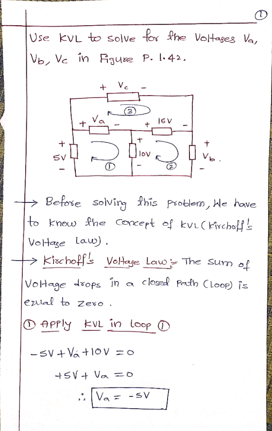
*P1.42. Use KVL to solve for the voltages va, vb, and VC in Figure P1.42. +...
Use Nodal Analysis to solve for VA, VB, VC, VG, l₁, l₂, I₃, V₁, V₂ and V₃
 Use Nodal Analysis to solve for VA, VB, VC, VG, l₁, l₂, I₃, V₁, V₂ and V₃ Conversion to Current Sources Not Required!Verify hand calculations using Multisim and insert screen capture results for each parameter. Use Digital Multimeters and/or Measurement Probes in Multisim to show output values for the voltages and currents in the circuit.
33. For the circuit of Figure 4.17, find voltages Va and Vb. Given: R1 = 3.14K...
 33. For the circuit of Figure 4.17, find voltages Va and Vb. Given: R1 = 3.14K IT = 2.93mA a 3k b Required: voltages Va and Vb. 10k 3 10 V = 4k 3 320k Ry=5.185k2 I= 1.93mA 33. V. - 10 V, V- 5.263 V 7 answers Solution: B:35.185 Va = 10V B = 3.41K12 I, - 341-2.93mA Vo= 10V -(1.92-3x_) = 4.2v
VA and vB identified in Figure 4 Use node voltage analysis to solve for the node...
 VA and vB identified in Figure 4 Use node voltage analysis to solve for the node voltages 4. 4 (k) 5 (mA) 10 (mA) 6 (k) 2 (k) Figure 4. Circuit for node voltage analysis for problem 4.
For the circuit shown, solve for VA, Vc, and Vp when VB= -5.00V, VE = 4.00V,...
 For the circuit shown, solve for VA, Vc, and Vp when VB= -5.00V, VE = 4.00V, and VF =3.00V. Express your answer to three significant figures using appropriate units. ► View Available Hint(s) +C Ve=4.00 V V3=-5.00 V VO F Ve=3.00 V
The node voltages are shown relative to the reference node e. If Va-1.045 V Vb-10.82-3.4 V...
 The node voltages are shown relative to the reference node e. If Va-1.045 V Vb-10.82-3.4 V Vc=3.0 -60.1° V Vd=9.82-45.8" V What is lx? 2Ω Selected Answer: b. 5.42-3.4° A
The node voltages are shown relative to the reference node e. If Va-1.0 5 v Vb-10.8-3.4°...
 The node voltages are shown relative to the reference node e. If Va-1.0 5 v Vb-10.8-3.4° v Vc-3.02-60.1° V Vd-9.8-45.8 v What is Ix ? V. 2? V. js2 o 6.9.-139.2° A
Neatly draw a diagram of two sine wave voltages, Va and Vb, where Va lags Vb...
Neatly draw a diagram of two sine wave voltages, Va and Vb, where Va lags Vb by 45 degrees.
The circuit shown in the figure below contains three resistors (R1, R2, three batteries (VA, V8,...
 The circuit shown in the figure below contains three resistors (R1, R2, three batteries (VA, V8, and Vc). The resistor values are: R1-2 Ohms, R2=R3=4 Ohms, and the battery voltages are Va=25 V, VB=15 V, and Vc=20 V. When the circuit is connected what will be the current through R2? VC R1 ** VA ++ VE R2 ho {} R3 0.75 A 1.25 A O 2.5 A O 3.0 A 375 A
620° V Find the two node voltages VA and VB and the output voltage V. in...
 620° V Find the two node voltages VA and VB and the output voltage V. in the circuit shown. i20 -1327 (120° A VO
The circuit shown in the figure below contains three resistors (R1, R2, and R3) and three...
 The circuit shown in the figure below contains three resistors
(R1, R2, and R3) and three batteries (VA, VB, and
VC). The resistor values are: R1=2 Ohms, R2=R3=6 Ohms,
and the battery voltages are VA=25 V, VB=15 V, and VC=20
V. When the circuit is connected, what will be the power
dissipated by R2?
VC HA R1 + + VA VB R2 M R3
The circuit shown in the figure below contains three resistors
(R1, R2, and R3) and three batteries (VA, VB, and
VC). The resistor values are: R1=2 Ohms, R2=R3=6 Ohms,
and the battery voltages are VA=25 V, VB=15 V, and VC=20
V. When the circuit is connected, what will be the power
dissipated by R2?
VC HA R1 + + VA VB R2 M R3
 33. For the circuit of Figure 4.17, find voltages Va and Vb. Given: R1 = 3.14K IT = 2.93mA a 3k b Required: voltages Va and Vb. 10k 3 10 V = 4k 3 320k Ry=5.185k2 I= 1.93mA 33. V. - 10 V, V- 5.263 V 7 answers Solution: B:35.185 Va = 10V B = 3.41K12 I, - 341-2.93mA Vo= 10V -(1.92-3x_) = 4.2v
 VA and vB identified in Figure 4 Use node voltage analysis to solve for the node voltages 4. 4 (k) 5 (mA) 10 (mA) 6 (k) 2 (k) Figure 4. Circuit for node voltage analysis for problem 4.
 For the circuit shown, solve for VA, Vc, and Vp when VB= -5.00V, VE = 4.00V, and VF =3.00V. Express your answer to three significant figures using appropriate units. ► View Available Hint(s) +C Ve=4.00 V V3=-5.00 V VO F Ve=3.00 V
 The node voltages are shown relative to the reference node e. If Va-1.045 V Vb-10.82-3.4 V Vc=3.0 -60.1° V Vd=9.82-45.8" V What is lx? 2Ω Selected Answer: b. 5.42-3.4° A
 The node voltages are shown relative to the reference node e. If Va-1.0 5 v Vb-10.8-3.4° v Vc-3.02-60.1° V Vd-9.8-45.8 v What is Ix ? V. 2? V. js2 o 6.9.-139.2° A
 The circuit shown in the figure below contains three resistors (R1, R2, three batteries (VA, V8, and Vc). The resistor values are: R1-2 Ohms, R2=R3=4 Ohms, and the battery voltages are Va=25 V, VB=15 V, and Vc=20 V. When the circuit is connected what will be the current through R2? VC R1 ** VA ++ VE R2 ho {} R3 0.75 A 1.25 A O 2.5 A O 3.0 A 375 A
 620° V Find the two node voltages VA and VB and the output voltage V. in the circuit shown. i20 -1327 (120° A VO
 The circuit shown in the figure below contains three resistors
(R1, R2, and R3) and three batteries (VA, VB, and
VC). The resistor values are: R1=2 Ohms, R2=R3=6 Ohms,
and the battery voltages are VA=25 V, VB=15 V, and VC=20
V. When the circuit is connected, what will be the power
dissipated by R2?
VC HA R1 + + VA VB R2 M R3
The circuit shown in the figure below contains three resistors
(R1, R2, and R3) and three batteries (VA, VB, and
VC). The resistor values are: R1=2 Ohms, R2=R3=6 Ohms,
and the battery voltages are VA=25 V, VB=15 V, and VC=20
V. When the circuit is connected, what will be the power
dissipated by R2?
VC HA R1 + + VA VB R2 M R3
Most questions answered within 3 hours.
-
Write the ionic equations for the first stage of salts
hydrolysis.
Anion, Cation?
Na2S
NiSO4
K2SO4...
asked 58 seconds from now -
suppose there is a normally distributed population with a mean of
250 and a standard deviation...
asked 42 minutes ago -
Question Three
Suppose you as project manager are using the Waterfall
development methodology on a large...
asked 1 hour ago -
Which statement is not true about welfare in Canada?
A.Benefits typically vary based on one's ability...
asked 2 hours ago -
Please help me with FLOWCHART and UML diagram for class,
thank you!
#include <iostream>
#include <fstream>...
asked 2 hours ago -
3. Describe the “logic circuit” of the Lac operon. Which
proteins are bound or not to...
asked 2 hours ago -
Ayesha’s adjusted gross income is $60,000 in 2019. She donated a
piece of artwork with a...
asked 3 hours ago -
For Dijkstra’s shortest path algorithm:
a. Give the Big-O time for Dijkstra’s shortest path algorithm
and...
asked 3 hours ago -
Phosphorus violates the 'octet rule' in biological molecules,
forming more covalent bonds than expected based on...
asked 3 hours ago -
A 1.3 eV electron has a 10-4 probability of tunneling
through a 2.4 eV potential barrier....
asked 3 hours ago -
What is the one ingredient that is common to being successful
with all stakeholders?
profit
trust...
asked 3 hours ago -
Write an assembly language 32 bit program that reads in lines of
text by a .txt...
asked 3 hours ago