
Homework Answers
 you can solve this problem by many methods
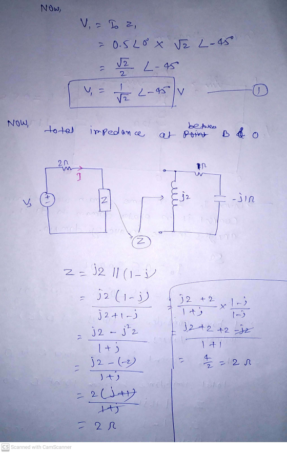
you need to just convert it into one domain, phasor domain
calculations are easy and simple so that better to go with phasor
domain calculations...
you can solve this problem by many methods
you need to just convert it into one domain, phasor domain
calculations are easy and simple so that better to go with phasor
domain calculations...
Thank you
Add Answer to:
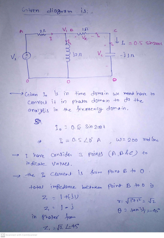
Q No 2. Given that current thru capacitor in the circuit below, Io = 0.5 Sin...
Find the charge q(t) on the capacitor and the current i(t) in the given LRC-series circuit....
 Find the charge q(t) on the capacitor and the current i(t) in the given LRC-series circuit. 5 h, R 2 1 f, E(t) 20 = 0 A 10 , C 200 V, q(0) 0 C, i(0) q(t) C i(t) A Find the maximum charge on the capacitor. (Round your answer to three decimal places.) C C II
Find the charge q(t) on the capacitor and the current i(t) in the given LRC-series circuit. 5 h, R 2 1 f, E(t)...
Find the charge q(t) on the capacitor and the current i(t) in the given LRC-series circuit. 5 h, R 2 1 f, E(t) 20 = 0 A 10 , C 200 V, q(0) 0 C, i(0) q(t) C i(t) A Find the maximum charge on the capacitor. (Round your answer to three decimal places.) C C II
Find the charge q(t) on the capacitor and the current i(t) in the given LRC-series circuit. 5 h, R 2 1 f, E(t)...
Suppose the current flowing thru a 10pF capacitor is 25 sin (10t+45°), find the phase of...
Suppose the current flowing thru a 10pF capacitor is 25 sin (10t+45°), find the phase of Vc(t)
Find the charge q(t) on the capacitor and the current i(t) in the given LRC-series circuit 1-1 h,...
 Find the charge q(t) on the capacitor and the current i(t) in the given LRC-series circuit 1-1 h, R-100 Ω, C-0.0004 f, E(t)-20 V, q(0)-0 C, i(0) 3 A Find the maximum charge on the capacitor. (Round your answer to four decimal places.) Need Help? Read It Talk to a Tutor
Find the charge q(t) on the capacitor and the current i(t) in the given LRC-series circuit 1-1 h, R-100 Ω, C-0.0004 f, E(t)-20 V, q(0)-0 C, i(0) 3 A...
Find the charge q(t) on the capacitor and the current i(t) in the given LRC-series circuit 1-1 h, R-100 Ω, C-0.0004 f, E(t)-20 V, q(0)-0 C, i(0) 3 A Find the maximum charge on the capacitor. (Round your answer to four decimal places.) Need Help? Read It Talk to a Tutor
Find the charge q(t) on the capacitor and the current i(t) in the given LRC-series circuit 1-1 h, R-100 Ω, C-0.0004 f, E(t)-20 V, q(0)-0 C, i(0) 3 A...
2) In an RLC circuit, ? = 10 Ω, ? = 0.5 ??, and ? =...
2) In an RLC circuit, ? = 10 Ω, ? = 0.5 ??, and ? = 6.0 ??, the current in the inductor is ?? = 12 ? sin(?? + 0.2). The circuit operates at half of the resonance frequency. a) Find the current in the resistor, capacitor and for the entire circuit. b) Find the voltage in the resistor, capacitor, and inductor. c) Find the emf of the AC source.
Question 4: RC Circuit: a) Charging capacitor: A simple RC circuit is given in Figure 4a....
 Question 4: RC Circuit: a) Charging capacitor: A simple RC circuit is given in Figure 4a. The capacitor is empty initially and switch was open for a long time. 4E, (V) EMF is used to charge the capacitor as switch is closed at t=0s. By using Kirchhoff's voltage law and Ohm's law that you learned so far, analyze this circuit and find the unknowns given below. 1)At t=0s. draw the equivalent circuit and find v. (Os), i. (Os), i (Os),...
In an RLC circuit, ? = 10 Ω, ? = 0.5 ??, and ? = 6.0...
 In an RLC circuit, ? = 10 Ω, ? = 0.5 ??, and ? = 6.0 ??, the
current in the inductor is ?? = 12 ? sin(?? + 0.2). The circuit
operates at half of the resonance frequency.
a) Find the current in the resistor, capacitor and for the
entire circuit.
b) Find the voltage in the resistor, capacitor, and
inductor.
c) Find the emf of the AC source.
Will give great review for good answer.
2) In an...
In an RLC circuit, ? = 10 Ω, ? = 0.5 ??, and ? = 6.0 ??, the
current in the inductor is ?? = 12 ? sin(?? + 0.2). The circuit
operates at half of the resonance frequency.
a) Find the current in the resistor, capacitor and for the
entire circuit.
b) Find the voltage in the resistor, capacitor, and
inductor.
c) Find the emf of the AC source.
Will give great review for good answer.
2) In an...
Problems 8 Look at the circuit below and find the current thru each resistor and the...
 Problems 8
Look at the circuit below and find the current thru each resistor and the voltage across each resistor. A series LRC circuit has R= 10 Ohms L = 40o mH, C = 2 microF, and an AC source with maximum voltage = 100 volts. The angular frequency is 4000 rad/s. What is the impedance of the circuit? What is the maximum current in the circuit? What is the maximum voltage across the capacitor?
Problems 8
Look at the circuit below and find the current thru each resistor and the voltage across each resistor. A series LRC circuit has R= 10 Ohms L = 40o mH, C = 2 microF, and an AC source with maximum voltage = 100 volts. The angular frequency is 4000 rad/s. What is the impedance of the circuit? What is the maximum current in the circuit? What is the maximum voltage across the capacitor?
In the circuit given below, V = 45 V and / = 9u(t) A. Find i(t)...
 In the circuit given below, V = 45 V and / = 9u(t) A. Find i(t) fort > 0. 10 22 www lico i(1) V 10 mF 4092 - 4H The current equation i(t) = [E+ (A091)+(Best) A, where A = B= S1 = s2 = and E= In the circuit given below, R=40. Find for t> 0. 492 ta X R WWW HH 1=0 / F 60 V H O 19 = -7.50 + [7.50 COS(8,731 +9.556 sin(8,731 ]e-11121...
Q.5. The op-amp in circuit shown below has a slew rate of 0.5 V/us. The amplifier...
 Q.5. The op-amp in circuit shown below has a slew rate of 0.5 V/us. The amplifier must be capable of amplifying the following signals: V1 = 0.1 sin (200 x 103 t) V2 0.2 sin (50 x 103 t) etermine whether the output will be distorted due to slew rate limitations. f yes, then (20 points) suggest remedy, other than changing the input. or 330v Vin 0.5。 33 X03.3 V
 Find the charge q(t) on the capacitor and the current i(t) in the given LRC-series circuit. 5 h, R 2 1 f, E(t) 20 = 0 A 10 , C 200 V, q(0) 0 C, i(0) q(t) C i(t) A Find the maximum charge on the capacitor. (Round your answer to three decimal places.) C C II
Find the charge q(t) on the capacitor and the current i(t) in the given LRC-series circuit. 5 h, R 2 1 f, E(t)...
Find the charge q(t) on the capacitor and the current i(t) in the given LRC-series circuit. 5 h, R 2 1 f, E(t) 20 = 0 A 10 , C 200 V, q(0) 0 C, i(0) q(t) C i(t) A Find the maximum charge on the capacitor. (Round your answer to three decimal places.) C C II
Find the charge q(t) on the capacitor and the current i(t) in the given LRC-series circuit. 5 h, R 2 1 f, E(t)...
 Find the charge q(t) on the capacitor and the current i(t) in the given LRC-series circuit 1-1 h, R-100 Ω, C-0.0004 f, E(t)-20 V, q(0)-0 C, i(0) 3 A Find the maximum charge on the capacitor. (Round your answer to four decimal places.) Need Help? Read It Talk to a Tutor
Find the charge q(t) on the capacitor and the current i(t) in the given LRC-series circuit 1-1 h, R-100 Ω, C-0.0004 f, E(t)-20 V, q(0)-0 C, i(0) 3 A...
Find the charge q(t) on the capacitor and the current i(t) in the given LRC-series circuit 1-1 h, R-100 Ω, C-0.0004 f, E(t)-20 V, q(0)-0 C, i(0) 3 A Find the maximum charge on the capacitor. (Round your answer to four decimal places.) Need Help? Read It Talk to a Tutor
Find the charge q(t) on the capacitor and the current i(t) in the given LRC-series circuit 1-1 h, R-100 Ω, C-0.0004 f, E(t)-20 V, q(0)-0 C, i(0) 3 A...
 Question 4: RC Circuit: a) Charging capacitor: A simple RC circuit is given in Figure 4a. The capacitor is empty initially and switch was open for a long time. 4E, (V) EMF is used to charge the capacitor as switch is closed at t=0s. By using Kirchhoff's voltage law and Ohm's law that you learned so far, analyze this circuit and find the unknowns given below. 1)At t=0s. draw the equivalent circuit and find v. (Os), i. (Os), i (Os),...
 In an RLC circuit, ? = 10 Ω, ? = 0.5 ??, and ? = 6.0 ??, the
current in the inductor is ?? = 12 ? sin(?? + 0.2). The circuit
operates at half of the resonance frequency.
a) Find the current in the resistor, capacitor and for the
entire circuit.
b) Find the voltage in the resistor, capacitor, and
inductor.
c) Find the emf of the AC source.
Will give great review for good answer.
2) In an...
In an RLC circuit, ? = 10 Ω, ? = 0.5 ??, and ? = 6.0 ??, the
current in the inductor is ?? = 12 ? sin(?? + 0.2). The circuit
operates at half of the resonance frequency.
a) Find the current in the resistor, capacitor and for the
entire circuit.
b) Find the voltage in the resistor, capacitor, and
inductor.
c) Find the emf of the AC source.
Will give great review for good answer.
2) In an...
 Problems 8
Look at the circuit below and find the current thru each resistor and the voltage across each resistor. A series LRC circuit has R= 10 Ohms L = 40o mH, C = 2 microF, and an AC source with maximum voltage = 100 volts. The angular frequency is 4000 rad/s. What is the impedance of the circuit? What is the maximum current in the circuit? What is the maximum voltage across the capacitor?
Problems 8
Look at the circuit below and find the current thru each resistor and the voltage across each resistor. A series LRC circuit has R= 10 Ohms L = 40o mH, C = 2 microF, and an AC source with maximum voltage = 100 volts. The angular frequency is 4000 rad/s. What is the impedance of the circuit? What is the maximum current in the circuit? What is the maximum voltage across the capacitor?
 In the circuit given below, V = 45 V and / = 9u(t) A. Find i(t) fort > 0. 10 22 www lico i(1) V 10 mF 4092 - 4H The current equation i(t) = [E+ (A091)+(Best) A, where A = B= S1 = s2 = and E= In the circuit given below, R=40. Find for t> 0. 492 ta X R WWW HH 1=0 / F 60 V H O 19 = -7.50 + [7.50 COS(8,731 +9.556 sin(8,731 ]e-11121...
 Q.5. The op-amp in circuit shown below has a slew rate of 0.5 V/us. The amplifier must be capable of amplifying the following signals: V1 = 0.1 sin (200 x 103 t) V2 0.2 sin (50 x 103 t) etermine whether the output will be distorted due to slew rate limitations. f yes, then (20 points) suggest remedy, other than changing the input. or 330v Vin 0.5。 33 X03.3 V
Most questions answered within 3 hours.
-
To be done in java code. 2 words are anagrams if 1 word can be
formed...
asked 6 minutes ago -
Bright Sun, Inc. sold an issue of 30-year $1,000 par value bonds
to the public. The...
asked 3 minutes ago -
Two players take turns at removing 1 to 4 coins from an original
pile of 16...
asked 3 minutes ago -
The income statement for the month of June, 2014 of Happy Smiles
Enterprises contains the following...
asked 9 minutes ago -
1-Calculate the mass in grams of 2.55 moles of KCl
2- Calculate how many moles are...
asked 9 minutes ago -
1. Choose value for p between 0.20 and 0.80. It should have at
least two decimal...
asked 10 minutes ago -
QUESTIONS: 500 words for the question
In defining abnormality, the criteria of “deviance”, “distress”
and “dysfunction”...
asked 12 minutes ago -
A sample of n = 25 scores produces a t statistic of t =
-2.062. If...
asked 30 minutes ago -
Given the following, compute the after tax cost of debt: The par
value of the firms...
asked 23 minutes ago -
Coding in C. Please only use stdio.h (which would mean no malloc
or anything like that)...
asked 29 minutes ago -
Use the fundamental accounting equation to find the missing
amounts.
Scenario
Assets
Liabilities
Equity
1
$...
asked 27 minutes ago -
A population has a mean of 200 and a standard deviation of 60.
Suppose a sample...
asked 31 minutes ago