

Homework Answers

Add Answer to:
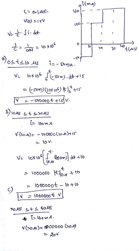
I need help with part D
The rectangular-shaped current pulse shown in the following figure is...
The triangular current pulse shown in (Figure 1) is applied to a 20 mH inductor. Use...
 The triangular current pulse shown in (Figure 1) is applied to a 20 mH inductor. Use the passive sign convention. O AEQ If vec ? y = Submit Request Answer Part F Derive the expression for the inductor voltage in the interval 0 <t<5 ms. Suppose that t is in seconds. Express your answer in volts in terms of t. TIVI AS01 1. vec ? Submit Request Answer Figure < 1 of 1 > Part G the interval ms <t<10...
I need help with part D-H Part A nstants For the capacitor network shown in (Figure...
 I need help with part D-H
Part A nstants For the capacitor network shown in (Figure 1), the potential difference across ab is 46 V Find the total charge stored in this network. Express your answer in microcoulombs to one decimal place Q3.1 C vious Answe Correct Significant Figures Feedback: Your answer 3.06 uC was either rounded differently or used a different number of significant figures than required for this part. Part B Find the charge on the 150 nF...
I need help with part D-H
Part A nstants For the capacitor network shown in (Figure 1), the potential difference across ab is 46 V Find the total charge stored in this network. Express your answer in microcoulombs to one decimal place Q3.1 C vious Answe Correct Significant Figures Feedback: Your answer 3.06 uC was either rounded differently or used a different number of significant figures than required for this part. Part B Find the charge on the 150 nF...
Problem 6.16 7 of 23 Review Constants An uncharged 0.2 μ capacitor is driven by a triangular current pulse. The current pulse is described by: t0s; O, 5000t A 10.2-50001 A, The vollage is described b...
 Problem 6.16 7 of 23 Review Constants An uncharged 0.2 μ capacitor is driven by a triangular current pulse. The current pulse is described by: t0s; O, 5000t A 10.2-50001 A, The vollage is described by: r(t) = 12.5 × 10,2 v 20 μ.<1<40pcs; t40 ps. 0, 0 s; 0st 20 us; 20 MS t-40 μ8; t40 s. - (loft-12.5 x 10":2-10) V, 10 V The power is described by: tS0s 0. p(t)-62.5 x 10¹²tt w 1>, 40μ. 0. The...
I need help with PART C. Consider the circuit sketched in the figure (Figure 1). The...
 I need help with PART C.
Consider the circuit sketched in the figure (Figure 1). The source has a voltage amplitude of 240 V, R = 160 Ohm, and the reactance of the capacitor is 660 Ohm. The voltage amplitude across the capacitor is 640 V. What is the current amplitude in the circuit? Express your answer in amperes to three significant figures. What is the impedance? Express your answer in ohms to three significant figures. What two values can...
I need help with PART C.
Consider the circuit sketched in the figure (Figure 1). The source has a voltage amplitude of 240 V, R = 160 Ohm, and the reactance of the capacitor is 660 Ohm. The voltage amplitude across the capacitor is 640 V. What is the current amplitude in the circuit? Express your answer in amperes to three significant figures. What is the impedance? Express your answer in ohms to three significant figures. What two values can...
Review Constants The current shown in (Figure 1) is applied to a 350 nF capacitor. The...
 Review Constants The current shown in (Figure 1) is applied to a 350 nF capacitor. The initial voltage on the capacitor is zero. Part A Find the charge on the capacitor at t = 30 jus Express your answer to three significant figures and include the appropriate units. IT μΑ q= 25.103 O Submit Previous Answers Request Answer Part B Find the voltage on the capacitor at t = 50 js. Express your answer to three significant figures and include...
Part D? The op amp in the circuit in (Figure 1) is ideal. Suppose R =...
 Part D?
The op amp in the circuit in (Figure 1) is ideal. Suppose R = 35 kΩ. Figure K 1 of 1 Σ 60 kΩ 30 ΚΩ 8 ΚΩ 15 V W X40 ΚΩ + 240 mV -15V Part A Calculate ia Express your answer to three significant figures and include the appropriate units. ia = 3.00x10⁻⁵ A Submit Previous Answers Correct Part B Calculate va Express your answer to three significant figures and include the appropriate units. Va...
Part D?
The op amp in the circuit in (Figure 1) is ideal. Suppose R = 35 kΩ. Figure K 1 of 1 Σ 60 kΩ 30 ΚΩ 8 ΚΩ 15 V W X40 ΚΩ + 240 mV -15V Part A Calculate ia Express your answer to three significant figures and include the appropriate units. ia = 3.00x10⁻⁵ A Submit Previous Answers Correct Part B Calculate va Express your answer to three significant figures and include the appropriate units. Va...
please help, if you're able to explain a-f that would be great, but i mainly need...
 please help, if you're able to explain a-f that would be great, but
i mainly need help with G
<Ch31. AC Circuits Part Part A Exercise 31.12 - Enhanced - with Feedback What is the impedance of the circuit? Express your answer with the appropriate units. What is the voltage amplitude across the resistor? Express your answer with the appropriate units. 2 = 251 VR = 19.7V Previous Answers Sube Previous Answers You have a 170 resistor, a 0.800 H...
please help, if you're able to explain a-f that would be great, but
i mainly need help with G
<Ch31. AC Circuits Part Part A Exercise 31.12 - Enhanced - with Feedback What is the impedance of the circuit? Express your answer with the appropriate units. What is the voltage amplitude across the resistor? Express your answer with the appropriate units. 2 = 251 VR = 19.7V Previous Answers Sube Previous Answers You have a 170 resistor, a 0.800 H...
The current shown in (Figure 1) is applied to a 600 nF capacitor. The initial voltage...
 The current shown in (Figure 1) is applied to a 600 nF capacitor. The initial voltage on the capacitor is zero. Part A Find the charge on the capacitor at t = 30 us. Express your answer to three significant figures and include the appropriate units. 4 = 4.50 C Submit Previous Answers Correct Part B Find the voltage on the capacitor at t = 50 js. Express your answer to three significant figures and include the appropriate units. HA...
Problem 1.20 The voltage and current at the terminals of the circuit element in (Figure 1)...
 Problem 1.20 The voltage and current at the terminals of the circuit element in (Figure 1) are zero fort < 0. u= (1500t + 1)e 750t V t> 0; i= 70e 7500 mA, t> 0. Part A where t is in seconds Find the time (in milliseconds) when the power delivered to the circuit element is maximum. Express your answer using three significant figures. t = 0 ms Submit Previous Answers Correct Part B Find the maximum value of p...
The voltage and current at the terminals of the element in (Figure 1) are Part D...
 The voltage and current at the terminals of the element in (Figure 1) are Part D v=230 cos 800nt V, i = 6 sin 800nt A. Find the average value of p in the interval 0 <t < 15.625 ms. Express your answer to three significant figures and include the appropriate units. ► View Available Hint(s) Figure < 1 of 1 > P p= 25.5 W + Submit Previous Answers X Incorrect; Try Again; 3 attempts remaining
 The triangular current pulse shown in (Figure 1) is applied to a 20 mH inductor. Use the passive sign convention. O AEQ If vec ? y = Submit Request Answer Part F Derive the expression for the inductor voltage in the interval 0 <t<5 ms. Suppose that t is in seconds. Express your answer in volts in terms of t. TIVI AS01 1. vec ? Submit Request Answer Figure < 1 of 1 > Part G the interval ms <t<10...
 I need help with part D-H
Part A nstants For the capacitor network shown in (Figure 1), the potential difference across ab is 46 V Find the total charge stored in this network. Express your answer in microcoulombs to one decimal place Q3.1 C vious Answe Correct Significant Figures Feedback: Your answer 3.06 uC was either rounded differently or used a different number of significant figures than required for this part. Part B Find the charge on the 150 nF...
I need help with part D-H
Part A nstants For the capacitor network shown in (Figure 1), the potential difference across ab is 46 V Find the total charge stored in this network. Express your answer in microcoulombs to one decimal place Q3.1 C vious Answe Correct Significant Figures Feedback: Your answer 3.06 uC was either rounded differently or used a different number of significant figures than required for this part. Part B Find the charge on the 150 nF...
 Problem 6.16 7 of 23 Review Constants An uncharged 0.2 μ capacitor is driven by a triangular current pulse. The current pulse is described by: t0s; O, 5000t A 10.2-50001 A, The vollage is described by: r(t) = 12.5 × 10,2 v 20 μ.<1<40pcs; t40 ps. 0, 0 s; 0st 20 us; 20 MS t-40 μ8; t40 s. - (loft-12.5 x 10":2-10) V, 10 V The power is described by: tS0s 0. p(t)-62.5 x 10¹²tt w 1>, 40μ. 0. The...
 I need help with PART C.
Consider the circuit sketched in the figure (Figure 1). The source has a voltage amplitude of 240 V, R = 160 Ohm, and the reactance of the capacitor is 660 Ohm. The voltage amplitude across the capacitor is 640 V. What is the current amplitude in the circuit? Express your answer in amperes to three significant figures. What is the impedance? Express your answer in ohms to three significant figures. What two values can...
I need help with PART C.
Consider the circuit sketched in the figure (Figure 1). The source has a voltage amplitude of 240 V, R = 160 Ohm, and the reactance of the capacitor is 660 Ohm. The voltage amplitude across the capacitor is 640 V. What is the current amplitude in the circuit? Express your answer in amperes to three significant figures. What is the impedance? Express your answer in ohms to three significant figures. What two values can...
 Review Constants The current shown in (Figure 1) is applied to a 350 nF capacitor. The initial voltage on the capacitor is zero. Part A Find the charge on the capacitor at t = 30 jus Express your answer to three significant figures and include the appropriate units. IT μΑ q= 25.103 O Submit Previous Answers Request Answer Part B Find the voltage on the capacitor at t = 50 js. Express your answer to three significant figures and include...
 Part D?
The op amp in the circuit in (Figure 1) is ideal. Suppose R = 35 kΩ. Figure K 1 of 1 Σ 60 kΩ 30 ΚΩ 8 ΚΩ 15 V W X40 ΚΩ + 240 mV -15V Part A Calculate ia Express your answer to three significant figures and include the appropriate units. ia = 3.00x10⁻⁵ A Submit Previous Answers Correct Part B Calculate va Express your answer to three significant figures and include the appropriate units. Va...
Part D?
The op amp in the circuit in (Figure 1) is ideal. Suppose R = 35 kΩ. Figure K 1 of 1 Σ 60 kΩ 30 ΚΩ 8 ΚΩ 15 V W X40 ΚΩ + 240 mV -15V Part A Calculate ia Express your answer to three significant figures and include the appropriate units. ia = 3.00x10⁻⁵ A Submit Previous Answers Correct Part B Calculate va Express your answer to three significant figures and include the appropriate units. Va...
 please help, if you're able to explain a-f that would be great, but
i mainly need help with G
<Ch31. AC Circuits Part Part A Exercise 31.12 - Enhanced - with Feedback What is the impedance of the circuit? Express your answer with the appropriate units. What is the voltage amplitude across the resistor? Express your answer with the appropriate units. 2 = 251 VR = 19.7V Previous Answers Sube Previous Answers You have a 170 resistor, a 0.800 H...
please help, if you're able to explain a-f that would be great, but
i mainly need help with G
<Ch31. AC Circuits Part Part A Exercise 31.12 - Enhanced - with Feedback What is the impedance of the circuit? Express your answer with the appropriate units. What is the voltage amplitude across the resistor? Express your answer with the appropriate units. 2 = 251 VR = 19.7V Previous Answers Sube Previous Answers You have a 170 resistor, a 0.800 H...
 The current shown in (Figure 1) is applied to a 600 nF capacitor. The initial voltage on the capacitor is zero. Part A Find the charge on the capacitor at t = 30 us. Express your answer to three significant figures and include the appropriate units. 4 = 4.50 C Submit Previous Answers Correct Part B Find the voltage on the capacitor at t = 50 js. Express your answer to three significant figures and include the appropriate units. HA...
 Problem 1.20 The voltage and current at the terminals of the circuit element in (Figure 1) are zero fort < 0. u= (1500t + 1)e 750t V t> 0; i= 70e 7500 mA, t> 0. Part A where t is in seconds Find the time (in milliseconds) when the power delivered to the circuit element is maximum. Express your answer using three significant figures. t = 0 ms Submit Previous Answers Correct Part B Find the maximum value of p...
 The voltage and current at the terminals of the element in (Figure 1) are Part D v=230 cos 800nt V, i = 6 sin 800nt A. Find the average value of p in the interval 0 <t < 15.625 ms. Express your answer to three significant figures and include the appropriate units. ► View Available Hint(s) Figure < 1 of 1 > P p= 25.5 W + Submit Previous Answers X Incorrect; Try Again; 3 attempts remaining
Most questions answered within 3 hours.
-
A car drives over the crest of a hill of radius 120m with a
speed of...
asked 9 minutes ago -
Implementation of a MapReduce-style distributed word count
application
For this assignment, you can use any programming...
asked 17 minutes ago -
In females, the labia swells and the vagin-a lubricates during
which phase of the sexual response...
asked 48 minutes ago -
2. An item costs a retailer $200. If a 30 percent markup is
desired, what should...
asked 50 minutes ago -
Your client, Anita, is hurt in a car accident and comes to you
for some advice....
asked 1 hour ago -
how many mL of 0.1050 M NaOH is needed to reach a pH of 3.74
when...
asked 57 minutes ago -
QUESTION
Memory retrieval that is easier when the person is in the same
psychological condition during...
asked 1 hour ago -
The mean annual inflation rate in the UNited States over the
past 98 years in 3.37%...
asked 1 hour ago -
Design a class Holiday that represents a
holiday during the year. This class has three
private...
asked 1 hour ago -
Problem 1 (Logistic Regression and KNN). In this problem, we
predict Direction using the data Weekly.csv....
asked 1 hour ago -
What is the difference between VNTRs (Variable Number Tandem
Repeats) and STRs (Short Tandem Repeats) used...
asked 1 hour ago -
Fill in
Isotope: 15 O
1. Element name:
2. Atomic number:
3. Mass number:
4. Number...
asked 1 hour ago