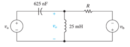
For the circuit in (Figure 1), suppose
va=10cos16,000tV,
vb=20cos4000tV.
Suppose that R = 350 Ω.
Part B
Write the steady-state expression for io(t) as io=I′ocos(ω′t+ϕ′)+I′′ocos(ω′′t+ϕ′′), where −180∘<ϕ′≤180∘, −180∘<ϕ′′≤180∘, and ω′>ω′′. Find the numerical value of I′o.
Express your answer to three significant figures and include the appropriate units.
Part C
Find the numerical value of ϕ′.
Express your answer using three significant figures.
Part D
Find the numerical value of ω′.
Express your answer using three significant figures.
Part E
Find the numerical value of I′′o.
Express your answer to three significant figures and include the appropriate units.
Part F
Find the numerical value of ϕ′′.
Express your answer using three significant figures.
Part G
Find the numerical value of ω′′.
Express your answer using three significant figures.
Homework Answers
![G2snf ato cos lbooot 仆- va - 孙リ 到.la (피a, (피 」400Q. 100 」400 Las, (0.0028 จ +o.oom] V.](http://img.homeworklib.com/questions/f062d890-0b3e-11ec-a563-a9ebc7b6dfec.png?x-oss-process=image/resize,w_560)


Add Answer to:
For the circuit in (Figure 1), suppose
va=10cos16,000tV,
vb=20cos4000tV.
Suppose that R = 350 Ω.
Part...
Consider the circuit shown in (Figure 1). Suppose that V, = 415 0°V (rms). 4 Ω...
 Consider the circuit shown in (Figure 1). Suppose that V, = 415 0°V (rms). 4 Ω ν j3ΩΙ 120 Ω + j90 Ω Source- Line - Load Find the average power dissipated in the line in the figure. Express your answer to three significant figures and include the appropriate units. t НА ? ? P= Value Units Find the capacitive reactance that, when connected in parallel, with the load will make the load look purely resistive. Express your answer to...
Use the node-voltage method to find the steady-state expression for io in the circuit seen in...
 Use the node-voltage method to find the steady-state expression
for io in the circuit seen in (Figure 1) if ig= 6 cos2500tA
and
vg= 20 cos(2500t+90∘)V.
Write the steady-state expression for io(t) as io=Iocos(ωt+ϕ),
where −180∘<ϕ≤180∘.
Assignment 8 Problem 9.56 13 of 19 > Review I Constants Part A Use the node-voltage method to find the steady-state expression ror io in the circuit seen in (Figure 1)T = 6 cos 2500t A and Find the numerical value of 2250090) V...
Use the node-voltage method to find the steady-state expression
for io in the circuit seen in (Figure 1) if ig= 6 cos2500tA
and
vg= 20 cos(2500t+90∘)V.
Write the steady-state expression for io(t) as io=Iocos(ωt+ϕ),
where −180∘<ϕ≤180∘.
Assignment 8 Problem 9.56 13 of 19 > Review I Constants Part A Use the node-voltage method to find the steady-state expression ror io in the circuit seen in (Figure 1)T = 6 cos 2500t A and Find the numerical value of 2250090) V...
Problem 4.90 PSpicelMultisim Part A The variable resistor (RL.) in the circuit in (Figure 1) is a...
 Problem 4.90 PSpicelMultisim Part A The variable resistor (RL.) in the circuit in (Figure 1) is adjusted for maximum power transfer to RI. Suppose that R:54 Ω Find the numerical value of RL Express your answer to three significant figures and include the appropriate units RL-Value Units Submit vio Figure Incorrect; Try Again; 4 attempts remaining Part B 30 0 Find the maximum power transferred to RI Express your answer to three significant figures and include the appropriate units 45...
The input to an op amp-based low-pass filter with a cutoff frequency of 500 Hz and...
The input to an op amp-based low-pass filter with a cutoff frequency of 500 Hz and a passband gain of 8 is 2.8cosωt V. Part A Part complete Suppose the power supplies are ±Vcc. What is the smallest value of Vcc that will still cause the op amp to operate in its linear region? Express your answer to three significant figures and include the appropriate units. Vccmin = 22.4 V (Correct) Part B Find the output voltage when ω=ωc.Suppose that...
Please box all answers for a thumbs up Consider the circuit shown in (Figure 1). Suppose...
 Please box all answers for a thumbs up
Consider the circuit shown in (Figure 1). Suppose that R = 7 kN. Figure K 1 of 1 Σ 40 ΚΩ 4 kΩ 2.5 kΩ 120 v 360 ΚΩ ()s.4 mA 390 kΩ 1.3 R 2 kΩ Part A Find the current i, in the circuit by making a succession of appropriate source transformations. Express your answer to three significant figures and include the appropriate units. μΑ ? io = Value mA...
Please box all answers for a thumbs up
Consider the circuit shown in (Figure 1). Suppose that R = 7 kN. Figure K 1 of 1 Σ 40 ΚΩ 4 kΩ 2.5 kΩ 120 v 360 ΚΩ ()s.4 mA 390 kΩ 1.3 R 2 kΩ Part A Find the current i, in the circuit by making a succession of appropriate source transformations. Express your answer to three significant figures and include the appropriate units. μΑ ? io = Value mA...
Part A The current and voltage at the terminals of the inductor in the circuit are...
 Part A The current and voltage at the terminals of the inductor in the circuit are i(t)=(3.4+3.8e-40t)A,t20; v(t)=-63e-40tV,t20+.(Figure 1) Specify the numerical value of V: - Express your answer to three significant figures and include the appropriate units. НА, ? V = Value Units Submit Request Answer Part B Specify the numerical value of R. Express your answer to three significant figures and include the appropriate units. HA ? R= Value Units Submit Request Answer Figure < 1 of 1...
reviewIwona Consider the circuit in (Figure 1). Suppose that i = 1.6 A and y =...
 reviewIwona Consider the circuit in (Figure 1). Suppose that i = 1.6 A and y = 28 V Part A Use a series of source transformations to find in in the circuit. Express your answer to three significant figures and include the appropriate units. View Available Hint(s) μΑ ? 0.399 A Submit Previous Answers X Incorrect: Try Again: 4 attempts remaining Part B Complete previous part(s) Provide Feedback Next > Figure 1 of 1 > 612 02 5 Ω w...
Use the node-voltage method to find the steady-state expression for vo(t) in the circuit in (Figure...
 Use the node-voltage method to find the steady-state expression
for vo(t) in the circuit in (Figure 1) if
vg1= 19 sin(400t+143.13∘)V,
vg2= 18.03cos(400t+33.69∘)V.
Write the steady-state expression for vo(t) as vo=Vocos(ωt+ϕ),
where −180∘<ϕ≤180∘.
EE 211/EE 212 FA19 Circuits Analysis for Engineers KEE 211/212 HW #10 -- Impedances, Sinusoidal Steady State Analysis Problem 9.57 PSpicelMultisim Use the node-voltage method to find the steady-state expression for (t) in the circuit in (Figure 1) if gl19 sin(400t143.13°) V. g218.03 cos(400t 33.69o) V. Write...
Use the node-voltage method to find the steady-state expression
for vo(t) in the circuit in (Figure 1) if
vg1= 19 sin(400t+143.13∘)V,
vg2= 18.03cos(400t+33.69∘)V.
Write the steady-state expression for vo(t) as vo=Vocos(ωt+ϕ),
where −180∘<ϕ≤180∘.
EE 211/EE 212 FA19 Circuits Analysis for Engineers KEE 211/212 HW #10 -- Impedances, Sinusoidal Steady State Analysis Problem 9.57 PSpicelMultisim Use the node-voltage method to find the steady-state expression for (t) in the circuit in (Figure 1) if gl19 sin(400t143.13°) V. g218.03 cos(400t 33.69o) V. Write...
- Part 6 Consider the circuit shown in (Figure 1). Suppose that in = 26 mA....
 - Part 6 Consider the circuit shown in (Figure 1). Suppose that in = 26 mA. 2 kn Find the magnitude of the total power absorbed in the circuit. Express your answer to three significant figures and include the appropriate units. 0 01342 6ka CHÁ A O O ? Value Units Part A Pabs – Determine the current i, in the circuit Express your unswer to three significant figures und include the uppropriule units. ? THÅR Value O ? Units...
Problem 9.56-Enhanced with Hints and Feedback Part A Review I Constants Find the numerical value of...
 Problem 9.56-Enhanced with Hints and Feedback Part A Review I Constants Find the numerical value of I Express your answer to three significant figures and include the appropriate units. Use the node-voltage method to find the steady-state expression for io in the circuit seen in (Figure 1) if i-5 cos 2500t A and vg-18 cos(2500t 90°) V Write the steady-state expression for io (t) as , = 10 cos(wt + φ), where _ 180° < φ 180° View Available Hint(s)...
 Consider the circuit shown in (Figure 1). Suppose that V, = 415 0°V (rms). 4 Ω ν j3ΩΙ 120 Ω + j90 Ω Source- Line - Load Find the average power dissipated in the line in the figure. Express your answer to three significant figures and include the appropriate units. t НА ? ? P= Value Units Find the capacitive reactance that, when connected in parallel, with the load will make the load look purely resistive. Express your answer to...
 Use the node-voltage method to find the steady-state expression
for io in the circuit seen in (Figure 1) if ig= 6 cos2500tA
and
vg= 20 cos(2500t+90∘)V.
Write the steady-state expression for io(t) as io=Iocos(ωt+ϕ),
where −180∘<ϕ≤180∘.
Assignment 8 Problem 9.56 13 of 19 > Review I Constants Part A Use the node-voltage method to find the steady-state expression ror io in the circuit seen in (Figure 1)T = 6 cos 2500t A and Find the numerical value of 2250090) V...
Use the node-voltage method to find the steady-state expression
for io in the circuit seen in (Figure 1) if ig= 6 cos2500tA
and
vg= 20 cos(2500t+90∘)V.
Write the steady-state expression for io(t) as io=Iocos(ωt+ϕ),
where −180∘<ϕ≤180∘.
Assignment 8 Problem 9.56 13 of 19 > Review I Constants Part A Use the node-voltage method to find the steady-state expression ror io in the circuit seen in (Figure 1)T = 6 cos 2500t A and Find the numerical value of 2250090) V...
 Problem 4.90 PSpicelMultisim Part A The variable resistor (RL.) in the circuit in (Figure 1) is adjusted for maximum power transfer to RI. Suppose that R:54 Ω Find the numerical value of RL Express your answer to three significant figures and include the appropriate units RL-Value Units Submit vio Figure Incorrect; Try Again; 4 attempts remaining Part B 30 0 Find the maximum power transferred to RI Express your answer to three significant figures and include the appropriate units 45...
 Please box all answers for a thumbs up
Consider the circuit shown in (Figure 1). Suppose that R = 7 kN. Figure K 1 of 1 Σ 40 ΚΩ 4 kΩ 2.5 kΩ 120 v 360 ΚΩ ()s.4 mA 390 kΩ 1.3 R 2 kΩ Part A Find the current i, in the circuit by making a succession of appropriate source transformations. Express your answer to three significant figures and include the appropriate units. μΑ ? io = Value mA...
Please box all answers for a thumbs up
Consider the circuit shown in (Figure 1). Suppose that R = 7 kN. Figure K 1 of 1 Σ 40 ΚΩ 4 kΩ 2.5 kΩ 120 v 360 ΚΩ ()s.4 mA 390 kΩ 1.3 R 2 kΩ Part A Find the current i, in the circuit by making a succession of appropriate source transformations. Express your answer to three significant figures and include the appropriate units. μΑ ? io = Value mA...
 Part A The current and voltage at the terminals of the inductor in the circuit are i(t)=(3.4+3.8e-40t)A,t20; v(t)=-63e-40tV,t20+.(Figure 1) Specify the numerical value of V: - Express your answer to three significant figures and include the appropriate units. НА, ? V = Value Units Submit Request Answer Part B Specify the numerical value of R. Express your answer to three significant figures and include the appropriate units. HA ? R= Value Units Submit Request Answer Figure < 1 of 1...
 reviewIwona Consider the circuit in (Figure 1). Suppose that i = 1.6 A and y = 28 V Part A Use a series of source transformations to find in in the circuit. Express your answer to three significant figures and include the appropriate units. View Available Hint(s) μΑ ? 0.399 A Submit Previous Answers X Incorrect: Try Again: 4 attempts remaining Part B Complete previous part(s) Provide Feedback Next > Figure 1 of 1 > 612 02 5 Ω w...
 Use the node-voltage method to find the steady-state expression
for vo(t) in the circuit in (Figure 1) if
vg1= 19 sin(400t+143.13∘)V,
vg2= 18.03cos(400t+33.69∘)V.
Write the steady-state expression for vo(t) as vo=Vocos(ωt+ϕ),
where −180∘<ϕ≤180∘.
EE 211/EE 212 FA19 Circuits Analysis for Engineers KEE 211/212 HW #10 -- Impedances, Sinusoidal Steady State Analysis Problem 9.57 PSpicelMultisim Use the node-voltage method to find the steady-state expression for (t) in the circuit in (Figure 1) if gl19 sin(400t143.13°) V. g218.03 cos(400t 33.69o) V. Write...
Use the node-voltage method to find the steady-state expression
for vo(t) in the circuit in (Figure 1) if
vg1= 19 sin(400t+143.13∘)V,
vg2= 18.03cos(400t+33.69∘)V.
Write the steady-state expression for vo(t) as vo=Vocos(ωt+ϕ),
where −180∘<ϕ≤180∘.
EE 211/EE 212 FA19 Circuits Analysis for Engineers KEE 211/212 HW #10 -- Impedances, Sinusoidal Steady State Analysis Problem 9.57 PSpicelMultisim Use the node-voltage method to find the steady-state expression for (t) in the circuit in (Figure 1) if gl19 sin(400t143.13°) V. g218.03 cos(400t 33.69o) V. Write...
 - Part 6 Consider the circuit shown in (Figure 1). Suppose that in = 26 mA. 2 kn Find the magnitude of the total power absorbed in the circuit. Express your answer to three significant figures and include the appropriate units. 0 01342 6ka CHÁ A O O ? Value Units Part A Pabs – Determine the current i, in the circuit Express your unswer to three significant figures und include the uppropriule units. ? THÅR Value O ? Units...
 Problem 9.56-Enhanced with Hints and Feedback Part A Review I Constants Find the numerical value of I Express your answer to three significant figures and include the appropriate units. Use the node-voltage method to find the steady-state expression for io in the circuit seen in (Figure 1) if i-5 cos 2500t A and vg-18 cos(2500t 90°) V Write the steady-state expression for io (t) as , = 10 cos(wt + φ), where _ 180° < φ 180° View Available Hint(s)...
Most questions answered within 3 hours.
-
PLEASE SHOW MATH CALCULATION(formulas)it has to be done on excel
P12-4 Last year (2016), Richter Condos...
asked 1 minute ago -
A 0.25μF capacitor is charged to 50 V . It is then connected in
series with...
asked 17 minutes ago -
Calculate the current, I, through the batteries for:
- a 2-bulb parallel circuit
- How does...
asked 19 minutes ago -
Choose the sentence that uses correct punctuation.
1a. The prefatory parts of a report include the...
asked 25 minutes ago -
For the element arsenic, which one of the following sets of
quantum numbers could not apply...
asked 34 minutes ago -
Compare and contrast the architectures of 3 types of ADCs:
Flash, SAR, and pipelined. Use the...
asked 35 minutes ago -
Given P(A) = 0.40, P(B) = 0.50, P(A ∩ B) = 0.15. Which of the
following...
asked 40 minutes ago -
Explain changes in workforce participation for women with
children. What legislation exists related to work and...
asked 42 minutes ago -
How high must a pointed arch be if it is to span a
space 4.2 m...
asked 47 minutes ago -
A housepainter who weighs 750 N stands 0.6 m from one end of a
2.0 m...
asked 49 minutes ago -
Implement Singly Linked List detectLoop in Java.
It would check whether the linked list contains a...
asked 52 minutes ago -
A small mailbag is released from a helicopter that is descending
steadily at 2.10 m/s.
After...
asked 53 minutes ago