

Homework Answers


Add Answer to:
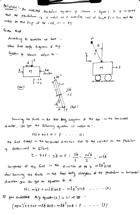
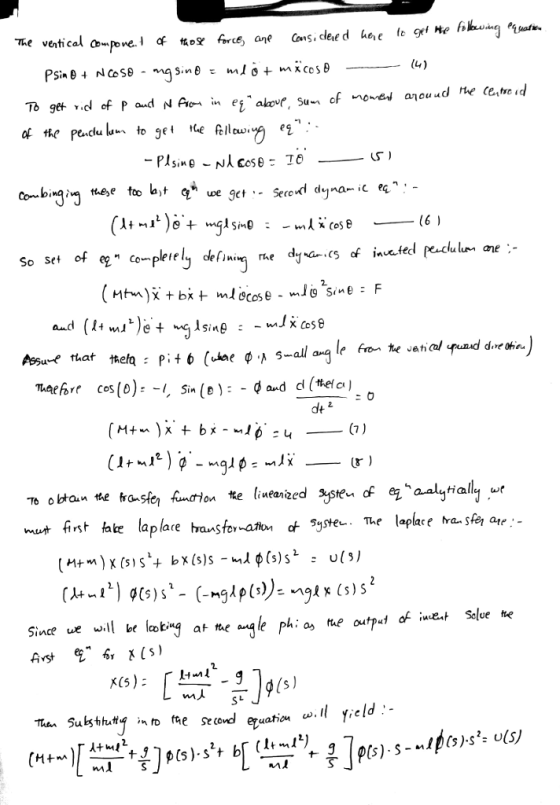
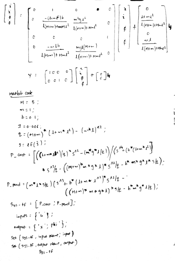
An inverted pendulum system is shown in Figure 1. It is assumed that the pendulum is...
Consider the inverted pendulum system presented in Fig. 1. The pivot of the pendulum is mounted o...
 Consider the inverted pendulum system presented in Fig. 1. The pivot of the pendulum is mounted on a cart, which can move in a horizontal direction. The pendulum can be kept balanced at a specific position by applying a horizontal force to drive the carriage. Assume that the pendulum mass, m, is concentrated ia at the end of the massless rod. The horizontal displacement of the pivot on the cart is x, the rotational angle of the pendulum is θ...
Consider the inverted pendulum system shown below. The inverted pendulum is mounted on top of a...
 Consider the inverted pendulum system shown below. The inverted pendulum is mounted on top of a motor driven cart. The pendulum and cart have two degrees of freedom in plane together, i.e x and θ. It is desired to keep the pendulum upright in the presence of disturbances, such as unexpected force applied on the cart. The slanted pendulum can be brought back to the vertical position by applying a control force u applied to the cart. Once the pendulum...
Consider the simple pendulum shown in the figure. The ball can be assumed to be a...
 Consider the simple pendulum shown in the figure. The ball can be assumed to be a concentrated mass of 10 kg attached to a massless rod of length 1=50 cm. a) Determine the period of oscillation of the simple pendulum b) If 8, = 12º and ., = 0 , find 0(t).
2. For the simple pendulum shown in Figure 2, the nonlinear equations of motion are given by θ(t)...
 do (b) and (c) only.
2. For the simple pendulum shown in Figure 2, the nonlinear equations of motion are given by θ(t) + 믈 sin θ(t) + m 0(t)-0 Pivot point L, length Massless rod , mass Figure 2. A simple pendulum 3. Consider again the pendulum of Figure 2 of problem 2 when g = 9.8 m/s, 1 = 4.9m, k =0.3, and (a) Determine whether the system is stable by finding the characteristic equation obtained from setting...
do (b) and (c) only.
2. For the simple pendulum shown in Figure 2, the nonlinear equations of motion are given by θ(t) + 믈 sin θ(t) + m 0(t)-0 Pivot point L, length Massless rod , mass Figure 2. A simple pendulum 3. Consider again the pendulum of Figure 2 of problem 2 when g = 9.8 m/s, 1 = 4.9m, k =0.3, and (a) Determine whether the system is stable by finding the characteristic equation obtained from setting...
Problem 2: Cart Standard Pendulum Model Consider the cart standard pendulum system shown in Figur...
 Problem 2: Cart Standard Pendulum Model Consider the cart standard pendulum system shown in Figure 1 with parameters given in Table 1 I C.8 I Ig Figure 1: Cart Standard Pendulum Schematic Syb Definition Unit Variablesr osition of the cart angle that the force applied on cart (control) mass of the cart mass ot t 123 lum makes with the vertic Parameters M5 kg utm 0.5 location of the c.g. of the pendulum above the 4 = m moment of...
Problem 6 State space representation of motor - driven cart with inverted pendulum You are given...
 Problem 6 State space representation of motor - driven cart with inverted pendulum You are given that the cart carrying the inverted pendulum shown in the figure below is driven by an electric motor powering one pair of wheels so that the whole cart, pendulum and all, becomes the load on the motor. z is the cart position, M is its mass, θ is the pendulum angle with respect to the vertical, I its length, and m its mass. The...
a cart moves at a constant acceleration a as shown in the figure below. a pendulum...
 a cart moves at a constant acceleration a as shown in
the figure below. a pendulum with a mass m is suspended from the
cart. calculate the angle that the pendulum cable makes with the
vertical.
ennls ur questions in your textbook. cart moves at a constant acceleration a as shown in the figure below. A per mass m is suspended from the cart. Calculate the angle θ that the pendulum ith the vertical. Explain clearly why the cable swings...
a cart moves at a constant acceleration a as shown in
the figure below. a pendulum with a mass m is suspended from the
cart. calculate the angle that the pendulum cable makes with the
vertical.
ennls ur questions in your textbook. cart moves at a constant acceleration a as shown in the figure below. A per mass m is suspended from the cart. Calculate the angle θ that the pendulum ith the vertical. Explain clearly why the cable swings...
Question 2 The pendulum shown in Figure 2 consists of a concentrated mass m attached to a rod who...
 Question 2 The pendulum shown in Figure 2 consists of a concentrated mass m attached to a rod whose mass is small compared to m. The rod's length is L. The equation of motion for this pendulum is Suppose that L 1 m and g 9.81 m/s2. Use MATLAB to solve this equation using symbolic and numerical techniques for, θ(t) for two cases: , θ(0)-0.5 rad and, θ(0)-0.8 rad. In both cases 0(0) 0. Figure 2- A pendulum [3 marks]...
Problem 3 (70 pts): Consider the mechanical system in Figure , the so-called "cart pendulum" system....
 Problem 3 (70 pts): Consider the mechanical system in Figure , the so-called "cart pendulum" system. The cart has a moving mass M, and is connected to a linear motor via a flexible coupling with stiffness K and damping B. An inverted pendulum of length1, negligible inertia and mass m is attached to the cart via a rotary actuator. If the pendulum damping coefficient is b, the linear actuator force is F and the rotary actuator torque is t 1)...
 Consider the inverted pendulum system presented in Fig. 1. The pivot of the pendulum is mounted on a cart, which can move in a horizontal direction. The pendulum can be kept balanced at a specific position by applying a horizontal force to drive the carriage. Assume that the pendulum mass, m, is concentrated ia at the end of the massless rod. The horizontal displacement of the pivot on the cart is x, the rotational angle of the pendulum is θ...
 Consider the inverted pendulum system shown below. The inverted pendulum is mounted on top of a motor driven cart. The pendulum and cart have two degrees of freedom in plane together, i.e x and θ. It is desired to keep the pendulum upright in the presence of disturbances, such as unexpected force applied on the cart. The slanted pendulum can be brought back to the vertical position by applying a control force u applied to the cart. Once the pendulum...
 Consider the simple pendulum shown in the figure. The ball can be assumed to be a concentrated mass of 10 kg attached to a massless rod of length 1=50 cm. a) Determine the period of oscillation of the simple pendulum b) If 8, = 12º and ., = 0 , find 0(t).
 do (b) and (c) only.
2. For the simple pendulum shown in Figure 2, the nonlinear equations of motion are given by θ(t) + 믈 sin θ(t) + m 0(t)-0 Pivot point L, length Massless rod , mass Figure 2. A simple pendulum 3. Consider again the pendulum of Figure 2 of problem 2 when g = 9.8 m/s, 1 = 4.9m, k =0.3, and (a) Determine whether the system is stable by finding the characteristic equation obtained from setting...
do (b) and (c) only.
2. For the simple pendulum shown in Figure 2, the nonlinear equations of motion are given by θ(t) + 믈 sin θ(t) + m 0(t)-0 Pivot point L, length Massless rod , mass Figure 2. A simple pendulum 3. Consider again the pendulum of Figure 2 of problem 2 when g = 9.8 m/s, 1 = 4.9m, k =0.3, and (a) Determine whether the system is stable by finding the characteristic equation obtained from setting...
 Problem 2: Cart Standard Pendulum Model Consider the cart standard pendulum system shown in Figure 1 with parameters given in Table 1 I C.8 I Ig Figure 1: Cart Standard Pendulum Schematic Syb Definition Unit Variablesr osition of the cart angle that the force applied on cart (control) mass of the cart mass ot t 123 lum makes with the vertic Parameters M5 kg utm 0.5 location of the c.g. of the pendulum above the 4 = m moment of...
 Problem 6 State space representation of motor - driven cart with inverted pendulum You are given that the cart carrying the inverted pendulum shown in the figure below is driven by an electric motor powering one pair of wheels so that the whole cart, pendulum and all, becomes the load on the motor. z is the cart position, M is its mass, θ is the pendulum angle with respect to the vertical, I its length, and m its mass. The...
 a cart moves at a constant acceleration a as shown in
the figure below. a pendulum with a mass m is suspended from the
cart. calculate the angle that the pendulum cable makes with the
vertical.
ennls ur questions in your textbook. cart moves at a constant acceleration a as shown in the figure below. A per mass m is suspended from the cart. Calculate the angle θ that the pendulum ith the vertical. Explain clearly why the cable swings...
a cart moves at a constant acceleration a as shown in
the figure below. a pendulum with a mass m is suspended from the
cart. calculate the angle that the pendulum cable makes with the
vertical.
ennls ur questions in your textbook. cart moves at a constant acceleration a as shown in the figure below. A per mass m is suspended from the cart. Calculate the angle θ that the pendulum ith the vertical. Explain clearly why the cable swings...
 Question 2 The pendulum shown in Figure 2 consists of a concentrated mass m attached to a rod whose mass is small compared to m. The rod's length is L. The equation of motion for this pendulum is Suppose that L 1 m and g 9.81 m/s2. Use MATLAB to solve this equation using symbolic and numerical techniques for, θ(t) for two cases: , θ(0)-0.5 rad and, θ(0)-0.8 rad. In both cases 0(0) 0. Figure 2- A pendulum [3 marks]...
 Problem 3 (70 pts): Consider the mechanical system in Figure , the so-called "cart pendulum" system. The cart has a moving mass M, and is connected to a linear motor via a flexible coupling with stiffness K and damping B. An inverted pendulum of length1, negligible inertia and mass m is attached to the cart via a rotary actuator. If the pendulum damping coefficient is b, the linear actuator force is F and the rotary actuator torque is t 1)...
Most questions answered within 3 hours.
-
The density of platinum is 21.45 g/mL. If a cube of platinum
with a mass of...
asked 3 minutes ago -
Accounts Receivable
Sales
A/R Posting
Extended Sales Invoice
Packing Slip
Compare invoice to packing slip 2...
asked 6 minutes ago -
Michaella, age 23, is a full-time law student and is claimed by
her parents as a...
asked 7 minutes ago -
Why are polymers not typically casted into products?
asked 24 minutes ago -
When rolling a die 129 times, what is the probability of rolling
a 6 no more...
asked 41 minutes ago -
4. A call option currently sells for $7.75. It has a strike
price of $85 and...
asked 30 minutes ago -
1.
You need to prepare 10.0 liters of an acid aqueous solution with a
pH of...
asked 32 minutes ago -
Along an aggregate supply curve, if the level of output is less
than the natural level...
asked 33 minutes ago -
By 2025, annual consumption in emerging markets will total $30
trillion and contribute more than ________...
asked 38 minutes ago -
At what point does reformation cease to be a viable option for
those who are oppressed...
asked 42 minutes ago -
Place letters corresponding to amounts in the proper order for
lightest to heaviest samples:
a) 2100...
asked 46 minutes ago -
Consider the multicore processor with 6 heterogeneous cores
labelled C1, C2, C3, C4, C5, and C6....
asked 49 minutes ago