
Homework Answers
Add Answer to:
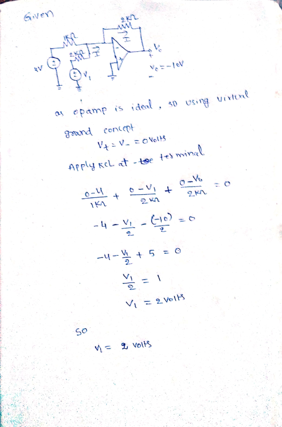
For the summing circuit shown below, find the voltage vi. 2k2 W 1k2 +) 4 V...
1. Find the numerical expression for the transfer function from Vi(t) to V.(t), for each circuit ...
 1. Find the numerical expression for the transfer function from Vi(t) to V.(t), for each circuit below, and sketch the magnitude and phase of the transfer function, as functions of w. For these plots, show the w axis on a log 10 scale, and show the amplitude of the transfer function on a decibel scale. 0.1uF V(t) 0.1 uF 250mH V(t) 250mH 2k2 V(t) 10k2 0.25μF Vo(t)
1. Find the numerical expression for the transfer function from Vi(t) to V.(t),...
1. Find the numerical expression for the transfer function from Vi(t) to V.(t), for each circuit below, and sketch the magnitude and phase of the transfer function, as functions of w. For these plots, show the w axis on a log 10 scale, and show the amplitude of the transfer function on a decibel scale. 0.1uF V(t) 0.1 uF 250mH V(t) 250mH 2k2 V(t) 10k2 0.25μF Vo(t)
1. Find the numerical expression for the transfer function from Vi(t) to V.(t),...
Consider the circuit shown below. V, changes from 0 V to 1.5 V at t =...
 Consider the circuit shown below. V, changes from 0 V to 1.5 V at t = 0 and remains at 1.5V. The transmission line has air between the conductors. {= 6 cm Rs=1502 WO w RL= 450 12 Vo=1.5V ( Zo=502 a) Find the following reflection coefficients: i. Tų (refl. coeff. at the load) ii. I's (refl. coeff. at the source) b) Complete the bounce diagram below by finding the values of the voltage pulses Vi+, Vi V2+, V2, V3+...
60 Lab Quiz circuit shown below, answer the following questions. (Show your calculations) R1 V1 L...
 60 Lab Quiz circuit shown below, answer the following questions. (Show your calculations) R1 V1 L1 R2 Figare 3 lab Quir RL. Cirewir 1. Write the storage phase equations for V1,V2·Yu and IL and calculate each at time 4m NOTE: Use R-1k2 when calculating the time constant.) 2. Calculate Vi, V2. VL. Is, 12, and Iu at steady-state (after the storage phase has passed.) 3. Calculate the voltage across the inductor (VL) just after the switch is opened (just beginning...
(1 point) Problem 5 In the circuit below, Vl = 4 V. V2 = 0.9 V....
 (1 point) Problem 5 In the circuit below, Vl = 4 V. V2 = 0.9 V. and RL = 1 .2kS2. Find vo Vi- RL 0
Can Someone explain how to do this problem? 4. Current and Voltage Source with Diode: For the circuit shown below, find...
 Can Someone explain how to do this problem?
4. Current and Voltage Source with Diode: For the circuit shown below, find the voltage vo. The current-voltage relationship for the diode is, as usual, Io(e"s/V 1) where Io 10-12 A and VT 0.026 V 10Ω 10 V (+ 5 mH Uo 1 A
4. Current and Voltage Source with Diode: For the circuit shown below, find the voltage vo. The current-voltage relationship for the diode is, as usual, Io(e"s/V 1) where...
Can Someone explain how to do this problem?
4. Current and Voltage Source with Diode: For the circuit shown below, find the voltage vo. The current-voltage relationship for the diode is, as usual, Io(e"s/V 1) where Io 10-12 A and VT 0.026 V 10Ω 10 V (+ 5 mH Uo 1 A
4. Current and Voltage Source with Diode: For the circuit shown below, find the voltage vo. The current-voltage relationship for the diode is, as usual, Io(e"s/V 1) where...
For the fullwave rectifier circuit shown below, the input voltage is Vi 6 sin 2n60t and...
 For the fullwave rectifier circuit shown below, the input voltage is Vi 6 sin 2n60t and the diodes D1, D2, D3, D4 each have a forward- voltage drop of 0.7 V when conducting. Determine the average value of the output voltage Vo (in V). (Enter your answer as a number without the units.)
4.0 First Circuit. The summing junction circuit Figure 2-4 below is the circuit for summing two...
 4.0 First Circuit. The summing junction circuit Figure 2-4 below is the circuit for summing two voltages, V, and V. The required components are an op-amp and resistors. Although the voltage are summed, the final summation is negative (I hope your experiment will prove this). This is what is called inverting op amp configuration. Nonetheless, the circuit sums Iwo voltages and is called summing circuit. 159 Tokom M Olhas -15 -IV ISV TOXO RA w 10km Vout 15V -ISV Figure...
Use superposition on the circuit below; a) Find the voltage V'1 due to the 12V voltage...
 Use superposition on the circuit below; a) Find the voltage V'1 due to the 12V voltage source alone. b) Find the voltage V": due to the 5mA current source alone. c) Find the total voltage V1 due to both sources. 2002 1002 12 4002 VI 5 mA 3002 www
Q1. For the filter circuit shown below, (5 marks) Vo(s) a) Find the transfer function, G(s)...
 Q1. For the filter circuit shown below, (5 marks) Vo(s) a) Find the transfer function, G(s) and the type of the filter. (4 marks) Vi(s)' b) Find the initial and final values of vo(t) if vi(t) = 2u(t). (1 marks) 10 k12 w 6 тн 0000 v;(1) 5 k92 2 mF
The input to the below op-amp circuit is the source voltage vi(t) and the response is...
 The input to the below op-amp circuit is the source voltage vi(t) and the response is the voltage across Rư, vo(t). Design this circuit to satisfy the following two specifications: (a) The phase shift at w = 1000 rad/s is 225 degree. (b) The gain at high frequencies is 10. Ri C = 0.1 uF vilo o Rız volt)
 1. Find the numerical expression for the transfer function from Vi(t) to V.(t), for each circuit below, and sketch the magnitude and phase of the transfer function, as functions of w. For these plots, show the w axis on a log 10 scale, and show the amplitude of the transfer function on a decibel scale. 0.1uF V(t) 0.1 uF 250mH V(t) 250mH 2k2 V(t) 10k2 0.25μF Vo(t)
1. Find the numerical expression for the transfer function from Vi(t) to V.(t),...
1. Find the numerical expression for the transfer function from Vi(t) to V.(t), for each circuit below, and sketch the magnitude and phase of the transfer function, as functions of w. For these plots, show the w axis on a log 10 scale, and show the amplitude of the transfer function on a decibel scale. 0.1uF V(t) 0.1 uF 250mH V(t) 250mH 2k2 V(t) 10k2 0.25μF Vo(t)
1. Find the numerical expression for the transfer function from Vi(t) to V.(t),...
 Consider the circuit shown below. V, changes from 0 V to 1.5 V at t = 0 and remains at 1.5V. The transmission line has air between the conductors. {= 6 cm Rs=1502 WO w RL= 450 12 Vo=1.5V ( Zo=502 a) Find the following reflection coefficients: i. Tų (refl. coeff. at the load) ii. I's (refl. coeff. at the source) b) Complete the bounce diagram below by finding the values of the voltage pulses Vi+, Vi V2+, V2, V3+...
 60 Lab Quiz circuit shown below, answer the following questions. (Show your calculations) R1 V1 L1 R2 Figare 3 lab Quir RL. Cirewir 1. Write the storage phase equations for V1,V2·Yu and IL and calculate each at time 4m NOTE: Use R-1k2 when calculating the time constant.) 2. Calculate Vi, V2. VL. Is, 12, and Iu at steady-state (after the storage phase has passed.) 3. Calculate the voltage across the inductor (VL) just after the switch is opened (just beginning...
 (1 point) Problem 5 In the circuit below, Vl = 4 V. V2 = 0.9 V. and RL = 1 .2kS2. Find vo Vi- RL 0
 Can Someone explain how to do this problem?
4. Current and Voltage Source with Diode: For the circuit shown below, find the voltage vo. The current-voltage relationship for the diode is, as usual, Io(e"s/V 1) where Io 10-12 A and VT 0.026 V 10Ω 10 V (+ 5 mH Uo 1 A
4. Current and Voltage Source with Diode: For the circuit shown below, find the voltage vo. The current-voltage relationship for the diode is, as usual, Io(e"s/V 1) where...
Can Someone explain how to do this problem?
4. Current and Voltage Source with Diode: For the circuit shown below, find the voltage vo. The current-voltage relationship for the diode is, as usual, Io(e"s/V 1) where Io 10-12 A and VT 0.026 V 10Ω 10 V (+ 5 mH Uo 1 A
4. Current and Voltage Source with Diode: For the circuit shown below, find the voltage vo. The current-voltage relationship for the diode is, as usual, Io(e"s/V 1) where...
 For the fullwave rectifier circuit shown below, the input voltage is Vi 6 sin 2n60t and the diodes D1, D2, D3, D4 each have a forward- voltage drop of 0.7 V when conducting. Determine the average value of the output voltage Vo (in V). (Enter your answer as a number without the units.)
 4.0 First Circuit. The summing junction circuit Figure 2-4 below is the circuit for summing two voltages, V, and V. The required components are an op-amp and resistors. Although the voltage are summed, the final summation is negative (I hope your experiment will prove this). This is what is called inverting op amp configuration. Nonetheless, the circuit sums Iwo voltages and is called summing circuit. 159 Tokom M Olhas -15 -IV ISV TOXO RA w 10km Vout 15V -ISV Figure...
 Use superposition on the circuit below; a) Find the voltage V'1 due to the 12V voltage source alone. b) Find the voltage V": due to the 5mA current source alone. c) Find the total voltage V1 due to both sources. 2002 1002 12 4002 VI 5 mA 3002 www
 Q1. For the filter circuit shown below, (5 marks) Vo(s) a) Find the transfer function, G(s) and the type of the filter. (4 marks) Vi(s)' b) Find the initial and final values of vo(t) if vi(t) = 2u(t). (1 marks) 10 k12 w 6 тн 0000 v;(1) 5 k92 2 mF
 The input to the below op-amp circuit is the source voltage vi(t) and the response is the voltage across Rư, vo(t). Design this circuit to satisfy the following two specifications: (a) The phase shift at w = 1000 rad/s is 225 degree. (b) The gain at high frequencies is 10. Ri C = 0.1 uF vilo o Rız volt)
Most questions answered within 3 hours.
-
Preparation of Benzoic Acid using a Grignard Reagent URGENT
1. During your Grignard formation, a small...
asked 19 minutes ago -
A uniform magnetic field is perpendicular to the plane of a wire
loop. If the loop...
asked 18 minutes ago -
At the peak of your career, your were earning $120,000 and
holding a top level position....
asked 21 minutes ago -
. A permanent magnet is dropped south-end-down through a horizontal
circular coil with a radius of...
asked 23 minutes ago -
Bernie's Beverages purchased some fixed assets classified as
5-year property for MACRS. The assets cost $28,000....
asked 37 minutes ago -
How many ATPs are produced from the catabolism of a 10-C
molecule of fatty acid under...
asked 42 minutes ago -
Before practicing a routine on the rings, a 64.8 kg gymnast
hangs motionless, with one hand...
asked 43 minutes ago -
If the K b of a weak base is 6.3 × 10 − 6 , what...
asked 50 minutes ago -
Which of the following is the minimum amount of moles of NaOH
that must be added...
asked 53 minutes ago -
Stories about organizational ________ provide important clues
about cultural values and norms.
a. myths
b. heroes...
asked 55 minutes ago -
Explain the criteria used in selecting a target market
BUS220 Retail Management, thank you!
asked 57 minutes ago -
Convert/Calculate the following:
Determine the identity of an elemental gas if 4.55 L weighing
35.4g, under...
asked 1 hour ago