
Homework Answers

![Pline - Wi rea part of Sine) u rea part of 1167.67 - j&as.9] 11 لک W dat = Pline 11 GG wi Average power dinspatted Optim-B Re](http://img.homeworklib.com/questions/fc9cbae0-170e-11ec-9b11-d11f400f1e63.png?x-oss-process=image/resize,w_560)

Add Answer to:
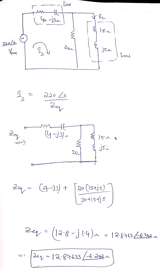
LINE 4.12 -;3.12 LOAD -wA 22020V 200 15.12 j52 Figure 1: For Question 6, 7 and...
1002 Figure 2: For Questions 8, 9, 10 For the circuit shown in Figure 2, Pi...
 1002 Figure 2: For Questions 8, 9, 10 For the circuit shown in Figure 2, Pi = 80 W with pf = 0.8 lagging, |S2| = 60 VA with pf = 0.7 leading, S3 = 40 VA with pf = 0.6 leading, I = 0.4237ºArms). Note that subscripts specify the load, so P1 is the real power for Load 1, which has impedance 21. 8. Determine P. (a) 57 W (b) 42 W (c) 36.63 W (d) 84.14 W (e)...
Consider the two loads in the circuit in (Figure 1). Load #1 (L1) absorbs S =...
 Consider the two loads in the
circuit in (Figure 1). Load #1 (L1) absorbs S = 56 VA at a lagging
power factor of pf = 0.61. Load #2 (L2) absorbs P2 = 56 W and Q2 =
1 VAR of power. If these loads are powered by a V = 425 V−rms ,
60-Hz source, what impedance needs to be added to the circuit in
order to raise the source's power factor to unity? Express your
answer in rectangular...
Consider the two loads in the
circuit in (Figure 1). Load #1 (L1) absorbs S = 56 VA at a lagging
power factor of pf = 0.61. Load #2 (L2) absorbs P2 = 56 W and Q2 =
1 VAR of power. If these loads are powered by a V = 425 V−rms ,
60-Hz source, what impedance needs to be added to the circuit in
order to raise the source's power factor to unity? Express your
answer in rectangular...
Problem 7 Re Consider the circuit shown in (Figure 1). Suppose that va = 130 cos...
 Problem 7 Re Consider the circuit shown in (Figure 1). Suppose that va = 130 cos 10,000+ V, where is in seconds. Part A Determine the load impedance for the circuit that will result in maximum average power being transferred to the load. Express your answer in ohms to three significant figures. Enter your answer in rectangular form. View Available Hints) 21 = 20.0 20.00 22 Previous Answers Correct Here we learn how to find the impedance of the circuit...
 1002 Figure 2: For Questions 8, 9, 10 For the circuit shown in Figure 2, Pi = 80 W with pf = 0.8 lagging, |S2| = 60 VA with pf = 0.7 leading, S3 = 40 VA with pf = 0.6 leading, I = 0.4237ºArms). Note that subscripts specify the load, so P1 is the real power for Load 1, which has impedance 21. 8. Determine P. (a) 57 W (b) 42 W (c) 36.63 W (d) 84.14 W (e)...
 Consider the two loads in the
circuit in (Figure 1). Load #1 (L1) absorbs S = 56 VA at a lagging
power factor of pf = 0.61. Load #2 (L2) absorbs P2 = 56 W and Q2 =
1 VAR of power. If these loads are powered by a V = 425 V−rms ,
60-Hz source, what impedance needs to be added to the circuit in
order to raise the source's power factor to unity? Express your
answer in rectangular...
Consider the two loads in the
circuit in (Figure 1). Load #1 (L1) absorbs S = 56 VA at a lagging
power factor of pf = 0.61. Load #2 (L2) absorbs P2 = 56 W and Q2 =
1 VAR of power. If these loads are powered by a V = 425 V−rms ,
60-Hz source, what impedance needs to be added to the circuit in
order to raise the source's power factor to unity? Express your
answer in rectangular...
 Problem 7 Re Consider the circuit shown in (Figure 1). Suppose that va = 130 cos 10,000+ V, where is in seconds. Part A Determine the load impedance for the circuit that will result in maximum average power being transferred to the load. Express your answer in ohms to three significant figures. Enter your answer in rectangular form. View Available Hints) 21 = 20.0 20.00 22 Previous Answers Correct Here we learn how to find the impedance of the circuit...
Most questions answered within 3 hours.
-
c++ program need help
Write a function allBigger that takes 3 parameters: 2 arrays of floats...
asked 15 minutes ago -
Underwater mortgages ~ A mortgage is termed “underwater” if the
amount owed is greater than the...
asked 14 minutes ago -
A 25ml pipet sample of an alcohol is found
asked 16 minutes ago -
8. The presidents of the past century have a mean height of 70.3
inches and a...
asked 19 minutes ago -
What do you think is the most difficult item for the union to
negotiate? Why?
asked 18 minutes ago -
Should non-profit organizations post their strategic plan on
their website? What about corporations? Why?
asked 34 minutes ago -
An unknown substance has a mass of 16.7 g. The temperature of
the substance increases by...
asked 43 minutes ago -
A toy cannon uses a spring to project a 5.21-g soft rubber ball.
The spring is...
asked 43 minutes ago -
what is balanced chemical equation including
states of matter of Nal + Na2CO3?
asked 42 minutes ago -
An archer shoots an arrow at a bottle. The arrow flys at 34m/s.
There is a...
asked 51 minutes ago -
Multiple choice data structures questions about stacks.
Here is an INCORRECT pseudocode for the algorithm which...
asked 57 minutes ago -
Osmotic forces related to protein concentration differences are
referred to as ________ forces.
asked 1 hour ago