
Homework Answers
If you have any doubts please comment
Thank you
If time permits please give feedback
Add Answer to:
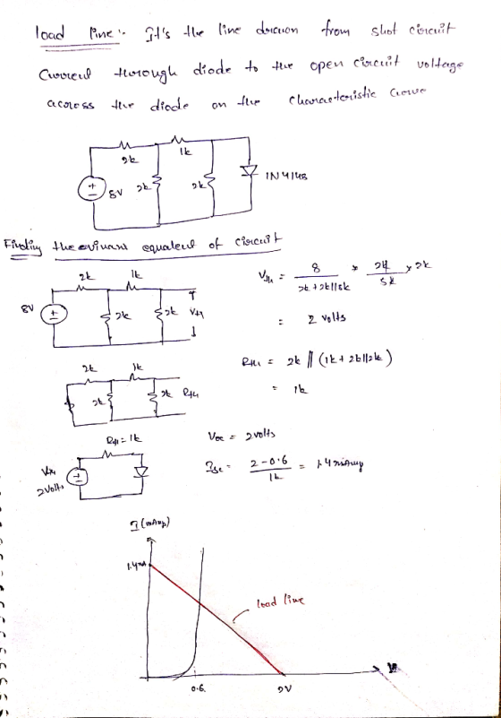
2) Draw the load line on the I-V curve given below for the following circuit. R1...
alright i need help finding the actual gain. the Vout RMS is off due to the DC offset. the peak to peak can be seen in...
 alright i need help finding the actual gain. the Vout RMS is off
due to the DC offset. the peak to peak can be seen in the pictures
noted with the arrows of the high and low.
V(vout) V (n002) Interval Start: 28ms V(vout) 4.4V Interval End: 50ms 4.0V Average: 3.3641V RMS: 3.3764V 3.6V Cancel 3.2V 2.8V 3.86 2.4V 2.87V 2.0V 1.6V 1.2V- 0.8V 0.4V LUL ЛЛ UП 0.0V --0.4V 28ms 30ms 32ms 34ms 36ms 38ms 40ms 42ms 44ms 46ms...
alright i need help finding the actual gain. the Vout RMS is off
due to the DC offset. the peak to peak can be seen in the pictures
noted with the arrows of the high and low.
V(vout) V (n002) Interval Start: 28ms V(vout) 4.4V Interval End: 50ms 4.0V Average: 3.3641V RMS: 3.3764V 3.6V Cancel 3.2V 2.8V 3.86 2.4V 2.87V 2.0V 1.6V 1.2V- 0.8V 0.4V LUL ЛЛ UП 0.0V --0.4V 28ms 30ms 32ms 34ms 36ms 38ms 40ms 42ms 44ms 46ms...
please solve in details. i will rate you up ! Problem 3 In the circuit shown...
 please solve in details. i will rate you up !
Problem 3 In the circuit shown below: a. Write a node equation at node 1 by summing the currents leaving node 1. b. Write a node equation at node 2 by summing the currents leaving node 2. c. Find V, and V2 by solving the two node equations. d. Find the currents IR, IR, IR3, IR4, Is. e. Find the power absorbed by R1, R2, R3, R4, and power released...
please solve in details. i will rate you up !
Problem 3 In the circuit shown below: a. Write a node equation at node 1 by summing the currents leaving node 1. b. Write a node equation at node 2 by summing the currents leaving node 2. c. Find V, and V2 by solving the two node equations. d. Find the currents IR, IR, IR3, IR4, Is. e. Find the power absorbed by R1, R2, R3, R4, and power released...
please solve these 2 problems. I will rate you up In the circuit shown below, let...
 please solve these 2 problems. I will rate you up
In the circuit shown below, let V. - 3 V.1. - 1 mA, R-3k, Ry - 2.5 kA, R = 1 kq Use mesh analysis to find mesh currents I, and 12. Also, find Vı. R1 V1 R2 W 2 is len 3kR 12 R3 100 IMA Problem 5 In the circuit shown below, let V, -8 V, 1. - 2 mA, R2 = 1 k 2, R2 = 400,...
please solve these 2 problems. I will rate you up
In the circuit shown below, let V. - 3 V.1. - 1 mA, R-3k, Ry - 2.5 kA, R = 1 kq Use mesh analysis to find mesh currents I, and 12. Also, find Vı. R1 V1 R2 W 2 is len 3kR 12 R3 100 IMA Problem 5 In the circuit shown below, let V, -8 V, 1. - 2 mA, R2 = 1 k 2, R2 = 400,...
About Exercise 8.4.9 In the phasor-domain circuit shown below. I-2/0° A, R1 -20 Ω, R2 1...
 About Exercise 8.4.9 In the phasor-domain circuit shown below. I-2/0° A, R1 -20 Ω, R2 1 Ω. R3 5 Ω.ZLI-JD Ω, ZL2-125 Ω, and R2 L a R3 Load L21 Determine S of the load.
why is R1 and R3 in series and not parallel? please help with calculations in this question. thanks! 23) Which of the following statements are true about the circuit below? I. R2 and R4 are in...
 why is R1 and R3 in series and not parallel?
please help with calculations in this question.
thanks!
23) Which of the following statements are true about the circuit below? I. R2 and R4 are in series. II. R2 and R4 are in parallel. IlI. R1 and R3 are in parallel. (D 150-Rv 24V 4,00-RJ D) L III A) I B) II C) III E-9 20) Which statements are true for the circuit shown in the figure below? The emf...
why is R1 and R3 in series and not parallel?
please help with calculations in this question.
thanks!
23) Which of the following statements are true about the circuit below? I. R2 and R4 are in series. II. R2 and R4 are in parallel. IlI. R1 and R3 are in parallel. (D 150-Rv 24V 4,00-RJ D) L III A) I B) II C) III E-9 20) Which statements are true for the circuit shown in the figure below? The emf...
6. Find Vi in the following circuit if VR2 3 V, I -2 A, RI 100...
 6. Find Vi in the following circuit if VR2 3 V, I -2 A, RI 100 , and R2 50 . Ry VR R.y 7. What is the output voltage (Vo) of the summing op-amp below? 1000 kn 200 k2 50 k2 +5 V 100 k2 -5 V V. out 8. For the operational amplifier circuit depicted below: a. Determine Vout in terms of the resistors: Ri, R2, R3, R4 and I R1 qut R- (current source) for the operational...
explain clearly and step by step using to study for final exam. will rate tthanks Problem 1: Consider the electrical circuit below and assume R1 = 12Ω, 10Ω, R3-9 Ω, R4-8 Ω, i,-3A, and v.-2 V. Using,...
 explain clearly and step by step using to study for final exam.
will rate tthanks
Problem 1: Consider the electrical circuit below and assume R1 = 12Ω, 10Ω, R3-9 Ω, R4-8 Ω, i,-3A, and v.-2 V. Using, Node-Voltage method, please, find the voltages vi, U2, v3 and the current i depicted in the figure. R1 Vs 1V2 VI RA releience Node .
Problem 1: Consider the electrical circuit below and assume R1 = 12Ω, 10Ω, R3-9 Ω, R4-8 Ω, i,-3A,...
explain clearly and step by step using to study for final exam.
will rate tthanks
Problem 1: Consider the electrical circuit below and assume R1 = 12Ω, 10Ω, R3-9 Ω, R4-8 Ω, i,-3A, and v.-2 V. Using, Node-Voltage method, please, find the voltages vi, U2, v3 and the current i depicted in the figure. R1 Vs 1V2 VI RA releience Node .
Problem 1: Consider the electrical circuit below and assume R1 = 12Ω, 10Ω, R3-9 Ω, R4-8 Ω, i,-3A,...
For the following design L1-2H C1-0.05F R1.4Ω R2-4Ω C2-0.05P L2-2H Va 4cos(10t+90°)V vb-4cos( 10t+90"N R4-4Ω R6:2Ω RS-4Ω Vc-4cos(20t+90jv vds4cos( 10t+60ον (Remember that i) w is given in ra...
 For the following design L1-2H C1-0.05F R1.4Ω R2-4Ω C2-0.05P L2-2H Va 4cos(10t+90°)V vb-4cos( 10t+90"N R4-4Ω R6:2Ω RS-4Ω Vc-4cos(20t+90jv vds4cos( 10t+60ον (Remember that i) w is given in rad/sec, ii) the above circuits have different Impedances for different frequencies, ii) we replace the shorted voltage power supplies with a short circuit, iV) with atjb the rectangular form and Ad the polar form we have a-Acos(8), b-Asin(θ), A-: va2+1,7 , θ= tan-l (4)if a > 0, θ= 180-tan-IL) if a <0) a)...
 alright i need help finding the actual gain. the Vout RMS is off
due to the DC offset. the peak to peak can be seen in the pictures
noted with the arrows of the high and low.
V(vout) V (n002) Interval Start: 28ms V(vout) 4.4V Interval End: 50ms 4.0V Average: 3.3641V RMS: 3.3764V 3.6V Cancel 3.2V 2.8V 3.86 2.4V 2.87V 2.0V 1.6V 1.2V- 0.8V 0.4V LUL ЛЛ UП 0.0V --0.4V 28ms 30ms 32ms 34ms 36ms 38ms 40ms 42ms 44ms 46ms...
alright i need help finding the actual gain. the Vout RMS is off
due to the DC offset. the peak to peak can be seen in the pictures
noted with the arrows of the high and low.
V(vout) V (n002) Interval Start: 28ms V(vout) 4.4V Interval End: 50ms 4.0V Average: 3.3641V RMS: 3.3764V 3.6V Cancel 3.2V 2.8V 3.86 2.4V 2.87V 2.0V 1.6V 1.2V- 0.8V 0.4V LUL ЛЛ UП 0.0V --0.4V 28ms 30ms 32ms 34ms 36ms 38ms 40ms 42ms 44ms 46ms...
 please solve in details. i will rate you up !
Problem 3 In the circuit shown below: a. Write a node equation at node 1 by summing the currents leaving node 1. b. Write a node equation at node 2 by summing the currents leaving node 2. c. Find V, and V2 by solving the two node equations. d. Find the currents IR, IR, IR3, IR4, Is. e. Find the power absorbed by R1, R2, R3, R4, and power released...
please solve in details. i will rate you up !
Problem 3 In the circuit shown below: a. Write a node equation at node 1 by summing the currents leaving node 1. b. Write a node equation at node 2 by summing the currents leaving node 2. c. Find V, and V2 by solving the two node equations. d. Find the currents IR, IR, IR3, IR4, Is. e. Find the power absorbed by R1, R2, R3, R4, and power released...
 please solve these 2 problems. I will rate you up
In the circuit shown below, let V. - 3 V.1. - 1 mA, R-3k, Ry - 2.5 kA, R = 1 kq Use mesh analysis to find mesh currents I, and 12. Also, find Vı. R1 V1 R2 W 2 is len 3kR 12 R3 100 IMA Problem 5 In the circuit shown below, let V, -8 V, 1. - 2 mA, R2 = 1 k 2, R2 = 400,...
please solve these 2 problems. I will rate you up
In the circuit shown below, let V. - 3 V.1. - 1 mA, R-3k, Ry - 2.5 kA, R = 1 kq Use mesh analysis to find mesh currents I, and 12. Also, find Vı. R1 V1 R2 W 2 is len 3kR 12 R3 100 IMA Problem 5 In the circuit shown below, let V, -8 V, 1. - 2 mA, R2 = 1 k 2, R2 = 400,...
 About Exercise 8.4.9 In the phasor-domain circuit shown below. I-2/0° A, R1 -20 Ω, R2 1 Ω. R3 5 Ω.ZLI-JD Ω, ZL2-125 Ω, and R2 L a R3 Load L21 Determine S of the load.
 why is R1 and R3 in series and not parallel?
please help with calculations in this question.
thanks!
23) Which of the following statements are true about the circuit below? I. R2 and R4 are in series. II. R2 and R4 are in parallel. IlI. R1 and R3 are in parallel. (D 150-Rv 24V 4,00-RJ D) L III A) I B) II C) III E-9 20) Which statements are true for the circuit shown in the figure below? The emf...
why is R1 and R3 in series and not parallel?
please help with calculations in this question.
thanks!
23) Which of the following statements are true about the circuit below? I. R2 and R4 are in series. II. R2 and R4 are in parallel. IlI. R1 and R3 are in parallel. (D 150-Rv 24V 4,00-RJ D) L III A) I B) II C) III E-9 20) Which statements are true for the circuit shown in the figure below? The emf...
 6. Find Vi in the following circuit if VR2 3 V, I -2 A, RI 100 , and R2 50 . Ry VR R.y 7. What is the output voltage (Vo) of the summing op-amp below? 1000 kn 200 k2 50 k2 +5 V 100 k2 -5 V V. out 8. For the operational amplifier circuit depicted below: a. Determine Vout in terms of the resistors: Ri, R2, R3, R4 and I R1 qut R- (current source) for the operational...
 explain clearly and step by step using to study for final exam.
will rate tthanks
Problem 1: Consider the electrical circuit below and assume R1 = 12Ω, 10Ω, R3-9 Ω, R4-8 Ω, i,-3A, and v.-2 V. Using, Node-Voltage method, please, find the voltages vi, U2, v3 and the current i depicted in the figure. R1 Vs 1V2 VI RA releience Node .
Problem 1: Consider the electrical circuit below and assume R1 = 12Ω, 10Ω, R3-9 Ω, R4-8 Ω, i,-3A,...
explain clearly and step by step using to study for final exam.
will rate tthanks
Problem 1: Consider the electrical circuit below and assume R1 = 12Ω, 10Ω, R3-9 Ω, R4-8 Ω, i,-3A, and v.-2 V. Using, Node-Voltage method, please, find the voltages vi, U2, v3 and the current i depicted in the figure. R1 Vs 1V2 VI RA releience Node .
Problem 1: Consider the electrical circuit below and assume R1 = 12Ω, 10Ω, R3-9 Ω, R4-8 Ω, i,-3A,...
 For the following design L1-2H C1-0.05F R1.4Ω R2-4Ω C2-0.05P L2-2H Va 4cos(10t+90°)V vb-4cos( 10t+90"N R4-4Ω R6:2Ω RS-4Ω Vc-4cos(20t+90jv vds4cos( 10t+60ον (Remember that i) w is given in rad/sec, ii) the above circuits have different Impedances for different frequencies, ii) we replace the shorted voltage power supplies with a short circuit, iV) with atjb the rectangular form and Ad the polar form we have a-Acos(8), b-Asin(θ), A-: va2+1,7 , θ= tan-l (4)if a > 0, θ= 180-tan-IL) if a <0) a)...
Most questions answered within 3 hours.
-
(Expected rate of return and risk) Carter Inc. is evaluating a
security. Calculate the investment’s expected...
asked 7 minutes ago -
What specific indicators can point to lack of progress for
African Americans in American society?
asked 1 hour ago -
1-The Electrons in a beam are moving at 2.7×10⁸ m/s in an
electric field of 15000...
asked 1 hour ago -
A gas tank is a vertical cylinder. It has a radius of 1m, a
height of...
asked 1 hour ago -
Accent Software faces the following conditions. All of these
support Accent’s use of a market-penetration pricing...
asked 2 hours ago -
A mathematically inclined friend emails you the following
instructions: "Meet me in the cafeteria the first...
asked 2 hours ago -
A monopoly sells in two countries . The demand curves in the two
countries are p1...
asked 3 hours ago -
A .15kg rubber ball is bounced off a wall. Before hitting the
wall, the ball moves...
asked 4 hours ago -
A manufacturing company preparing to build a new plant is
considering three potential locations for it....
asked 4 hours ago -
B. If compound Y has approximately the same values of solubility
in toluene as compound X,...
asked 5 hours ago -
Oscar Inc. has inventory in Japan valued at 39,051,000 Yen one
year ago. One year ago...
asked 5 hours ago -
If Canada suffered from "fundamental disequilibrium," and its
government choose not to devalue its currency, a...
asked 5 hours ago