

Homework Answers
![0 => if t) = (4.5+69+) et A de = (4.5-94) etc) + ét (-2) dillot) + = -45 - - -|3.5 Velt) = 26-4.5tet +9e-t] duc Cats La sté?](http://img.homeworklib.com/questions/5a8fb660-1a3a-11ec-8769-97d7023f7486.png?x-oss-process=image/resize,w_560)
Add Answer to:
5.) In the series RLC circuit shown in Figure 2, switches S1 and 52 both open...
0 in the series RLC circuit shown in Figure 2 switches 51 and 52 both open...
 0 in the series RLC circuit shown in Figure 2 switches 51 and 52 both open at t -0. Solve the differential equation for loop current I (t) when the res has a value of 1 Ohm. Be sure to show all work and specify values for alpha, WO, W d, S1, S2, (o), V(o), etc. if they are required for the solution (e.g. s1 and s2 are only needed for an overdamped solution. (300 pts a: - Wo =...
A second-order RLC circuit is shown in Fig. 1 0.05F 3Ω 2Ω 6A 6A 5H Fig.1 A second-order RLC cir...
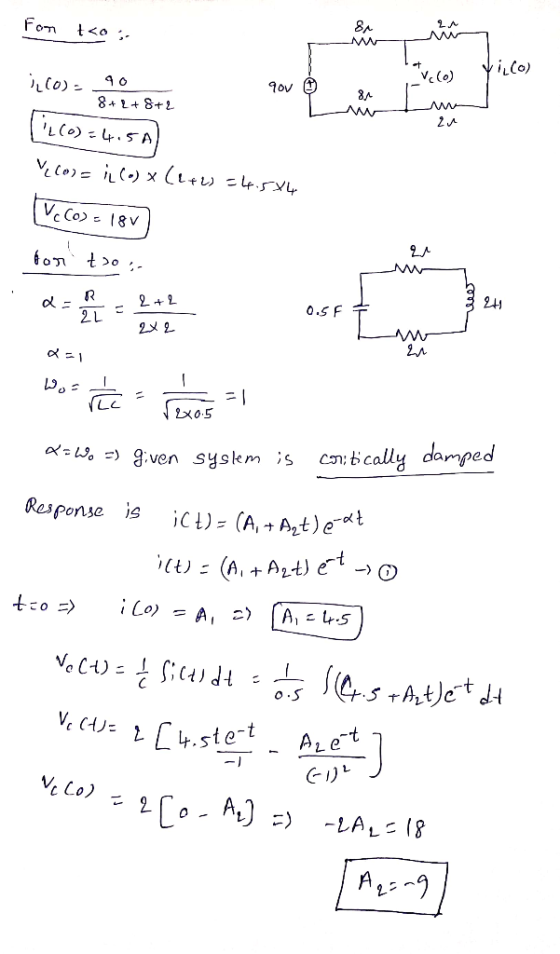
 A second-order RLC circuit is shown in Fig. 1 0.05F 3Ω 2Ω 6A 6A 5H Fig.1 A second-order RLC circuit with a switch (1) Analytical part: derive the differential equations and solve them to find the response i(t for t>0. Specify whether it is an underdamped, critically damped or overdamped case.
A second-order RLC circuit is shown in Fig. 1
0.05F 3Ω 2Ω 6A 6A 5H Fig.1 A second-order RLC circuit with a switch (1) Analytical part: derive the differential...
A second-order RLC circuit is shown in Fig. 1 0.05F 3Ω 2Ω 6A 6A 5H Fig.1 A second-order RLC circuit with a switch (1) Analytical part: derive the differential equations and solve them to find the response i(t for t>0. Specify whether it is an underdamped, critically damped or overdamped case.
A second-order RLC circuit is shown in Fig. 1
0.05F 3Ω 2Ω 6A 6A 5H Fig.1 A second-order RLC circuit with a switch (1) Analytical part: derive the differential...
Problem 5: Consider the circuit shown in the figure below in which the initial inductor current...
 Problem 5: Consider the circuit shown in the figure below in which the initial inductor current and capacitor voltage are both zero. (a) Write the differential equation for vc(t). (b) Find the particular solution. (c) Is this circuit overdamped, critically damped, or underdamped? 4 0 i(t) vc()
Function Generatr Inductor Model Ra R, Figure 1 Series RLC Circuit Preliminary This laboratory wi...
 Function Generatr Inductor Model Ra R, Figure 1 Series RLC Circuit Preliminary This laboratory will demonstrate how varying resistance changes the natural response of a series RLC circuit (Fig. 1). The function generator is modeled as an ideal voltage source v(t) 5 u() V in series with source resistance Rs-50Q. After measurements using an LCR meter, the inductor is modeled as an ideal L 90 mH inductor in series with resistance RL-20Q. The capacitance is C-0.22 μF. 1) Calculate the...
2. Charge-up response of series RLC circuit. No energy is stored in the 0.1H inductor or...
 2. Charge-up response of series RLC circuit. No energy is stored in the 0.1H inductor or the 0.4uF capacitor before the switch in the circuit shown in the figure below is closed. Find S2 Key= A 2800 1. 0.4uF - 3. Discharge response of series RLC circuit. The circuit had been in steady state prior to moving the switch at t=0. Find = Key = Space Key C1 0.44F For both circuits: a) Is the response underdamped, overdamped, or critically...
The answer key says Underdamped, but i do not understand why. Question 10 In the circuit below, the inductor current, iz(), for t2 0 is known to be, -10t 1012 ve(t)) Vc(t) Find the response curve tha...
 The answer key says Underdamped, but i do not understand
why.
Question 10 In the circuit below, the inductor current, iz(), for t2 0 is known to be, -10t 1012 ve(t)) Vc(t) Find the response curve that best represents the inductor current above iL(t) iL(t) (2) Underdamped (1) Undamped it t) i(t) (4) Overdamped (3) Critically damped (5) None of the above
Question 10 In the circuit below, the inductor current, iz(), for t2 0 is known to be, -10t...
The answer key says Underdamped, but i do not understand
why.
Question 10 In the circuit below, the inductor current, iz(), for t2 0 is known to be, -10t 1012 ve(t)) Vc(t) Find the response curve that best represents the inductor current above iL(t) iL(t) (2) Underdamped (1) Undamped it t) i(t) (4) Overdamped (3) Critically damped (5) None of the above
Question 10 In the circuit below, the inductor current, iz(), for t2 0 is known to be, -10t...
Section 3: Laplace transform for RLC circuit analysis (10 marks) A second-order RLC circuit with a...
 Section 3: Laplace transform for RLC circuit analysis (10 marks) A second-order RLC circuit with a dependent source is shown in Fig. 3. 22 + VO - 132 1F + 15e-2 u(t) V ) 9[1-u(t)] V Y 0.50 » Fig. 3 A second-order RLC circuit with a dependent source Take the Laplace transform of the circuit and hence find the response io(t) for t > 0. Specify whether it is an underdamped, critically damped or overdamped case. Sketch the response.
3. Use the circuit below to answer the following questions. The switch has been in the...
 3. Use the circuit below to answer the following questions. The switch has been in the initial position shown for a long time. At t=0, the switch disconnects the 2 V source from the circuit with R2, L1, and Ci, and connects to Il and Ri. S1 t=0 R2 L1 1000 33mH 1A 31000 2v C1 +1 47uF Fill in the table below. Please remember to include units with your answers. Immediately before 1-0. Immediately after 1-0. Long after 1...
The switch in the circuit of Figure 1 has been in position A for a long...
 The switch in the circuit of Figure 1 has been in position A for a long time. At t-0, it is moved to position B The resulting step response of the series RLC circuit is described by the r differential equation (1). Figure 1 dt L dt LC LC The solution to equation (1) has two components the transient response vt(t) and the steady state response, Vss(t) v(t)v(t)+ Vss(t) The transient response v(t) is the same as that for the...
A circuit is wired up as shown below. The capacitor is initially uncharged and switches S1 and S2 are initially open.
 A circuit is wired up as shown below. The capacitor is initially uncharged and switches S1 and S2 are initially open.1) What is the voltage across the capacitor immediately after
switch S1 is closed?Vc = 0Vc = VVc = 2V/32) What is the voltage across the capacitor after switch S1 has
been closed for a very long time?Vc = 0Vc = VVc = 2V/33) After being closed a long time, switch 1 is opened and switch
2 is closed. What...
A circuit is wired up as shown below. The capacitor is initially uncharged and switches S1 and S2 are initially open.1) What is the voltage across the capacitor immediately after
switch S1 is closed?Vc = 0Vc = VVc = 2V/32) What is the voltage across the capacitor after switch S1 has
been closed for a very long time?Vc = 0Vc = VVc = 2V/33) After being closed a long time, switch 1 is opened and switch
2 is closed. What...
 0 in the series RLC circuit shown in Figure 2 switches 51 and 52 both open at t -0. Solve the differential equation for loop current I (t) when the res has a value of 1 Ohm. Be sure to show all work and specify values for alpha, WO, W d, S1, S2, (o), V(o), etc. if they are required for the solution (e.g. s1 and s2 are only needed for an overdamped solution. (300 pts a: - Wo =...
 A second-order RLC circuit is shown in Fig. 1 0.05F 3Ω 2Ω 6A 6A 5H Fig.1 A second-order RLC circuit with a switch (1) Analytical part: derive the differential equations and solve them to find the response i(t for t>0. Specify whether it is an underdamped, critically damped or overdamped case.
A second-order RLC circuit is shown in Fig. 1
0.05F 3Ω 2Ω 6A 6A 5H Fig.1 A second-order RLC circuit with a switch (1) Analytical part: derive the differential...
A second-order RLC circuit is shown in Fig. 1 0.05F 3Ω 2Ω 6A 6A 5H Fig.1 A second-order RLC circuit with a switch (1) Analytical part: derive the differential equations and solve them to find the response i(t for t>0. Specify whether it is an underdamped, critically damped or overdamped case.
A second-order RLC circuit is shown in Fig. 1
0.05F 3Ω 2Ω 6A 6A 5H Fig.1 A second-order RLC circuit with a switch (1) Analytical part: derive the differential...
 Problem 5: Consider the circuit shown in the figure below in which the initial inductor current and capacitor voltage are both zero. (a) Write the differential equation for vc(t). (b) Find the particular solution. (c) Is this circuit overdamped, critically damped, or underdamped? 4 0 i(t) vc()
 Function Generatr Inductor Model Ra R, Figure 1 Series RLC Circuit Preliminary This laboratory will demonstrate how varying resistance changes the natural response of a series RLC circuit (Fig. 1). The function generator is modeled as an ideal voltage source v(t) 5 u() V in series with source resistance Rs-50Q. After measurements using an LCR meter, the inductor is modeled as an ideal L 90 mH inductor in series with resistance RL-20Q. The capacitance is C-0.22 μF. 1) Calculate the...
 2. Charge-up response of series RLC circuit. No energy is stored in the 0.1H inductor or the 0.4uF capacitor before the switch in the circuit shown in the figure below is closed. Find S2 Key= A 2800 1. 0.4uF - 3. Discharge response of series RLC circuit. The circuit had been in steady state prior to moving the switch at t=0. Find = Key = Space Key C1 0.44F For both circuits: a) Is the response underdamped, overdamped, or critically...
 The answer key says Underdamped, but i do not understand
why.
Question 10 In the circuit below, the inductor current, iz(), for t2 0 is known to be, -10t 1012 ve(t)) Vc(t) Find the response curve that best represents the inductor current above iL(t) iL(t) (2) Underdamped (1) Undamped it t) i(t) (4) Overdamped (3) Critically damped (5) None of the above
Question 10 In the circuit below, the inductor current, iz(), for t2 0 is known to be, -10t...
The answer key says Underdamped, but i do not understand
why.
Question 10 In the circuit below, the inductor current, iz(), for t2 0 is known to be, -10t 1012 ve(t)) Vc(t) Find the response curve that best represents the inductor current above iL(t) iL(t) (2) Underdamped (1) Undamped it t) i(t) (4) Overdamped (3) Critically damped (5) None of the above
Question 10 In the circuit below, the inductor current, iz(), for t2 0 is known to be, -10t...
 Section 3: Laplace transform for RLC circuit analysis (10 marks) A second-order RLC circuit with a dependent source is shown in Fig. 3. 22 + VO - 132 1F + 15e-2 u(t) V ) 9[1-u(t)] V Y 0.50 » Fig. 3 A second-order RLC circuit with a dependent source Take the Laplace transform of the circuit and hence find the response io(t) for t > 0. Specify whether it is an underdamped, critically damped or overdamped case. Sketch the response.
 3. Use the circuit below to answer the following questions. The switch has been in the initial position shown for a long time. At t=0, the switch disconnects the 2 V source from the circuit with R2, L1, and Ci, and connects to Il and Ri. S1 t=0 R2 L1 1000 33mH 1A 31000 2v C1 +1 47uF Fill in the table below. Please remember to include units with your answers. Immediately before 1-0. Immediately after 1-0. Long after 1...
 The switch in the circuit of Figure 1 has been in position A for a long time. At t-0, it is moved to position B The resulting step response of the series RLC circuit is described by the r differential equation (1). Figure 1 dt L dt LC LC The solution to equation (1) has two components the transient response vt(t) and the steady state response, Vss(t) v(t)v(t)+ Vss(t) The transient response v(t) is the same as that for the...
 A circuit is wired up as shown below. The capacitor is initially uncharged and switches S1 and S2 are initially open.1) What is the voltage across the capacitor immediately after
switch S1 is closed?Vc = 0Vc = VVc = 2V/32) What is the voltage across the capacitor after switch S1 has
been closed for a very long time?Vc = 0Vc = VVc = 2V/33) After being closed a long time, switch 1 is opened and switch
2 is closed. What...
A circuit is wired up as shown below. The capacitor is initially uncharged and switches S1 and S2 are initially open.1) What is the voltage across the capacitor immediately after
switch S1 is closed?Vc = 0Vc = VVc = 2V/32) What is the voltage across the capacitor after switch S1 has
been closed for a very long time?Vc = 0Vc = VVc = 2V/33) After being closed a long time, switch 1 is opened and switch
2 is closed. What...
Most questions answered within 3 hours.
-
A customer has requested that Lewelling Corporation fill a
special order for 2,400 units of product...
asked 10 minutes ago -
What are two strengths and two weaknesses of hardware,
software, and/or data?
How can the weaknesses...
asked 13 minutes ago -
A and B face the choice of working in a safe
mine at €200/wk or an...
asked 33 minutes ago -
True or false: couldnt figure out these few
- When charges are only located OUTSIDE an...
asked 41 minutes ago -
Given the following function:
int fun1(int count){
int Num ;
for (i = 0; i <...
asked 42 minutes ago -
Please submit your paper topic so that I can review it and make
any necessary suggestions...
asked 42 minutes ago -
Why are there so many theories of addiction? (Consider the
adequacy of each theory in relation...
asked 46 minutes ago -
22mL of 0.1020M Naoh is used in a titration against an unknown
1M acid (30mL). Determine...
asked 54 minutes ago -
Solve for distance using 90 db = 85 db + 20 log (20 ft/
distance)
1.8...
asked 56 minutes ago -
Aluminum is cast in an insulating ceramic mold with no
superheat. The thickness of the casting...
asked 1 hour ago -
Discuss the current status of Ulmus americana and the reasons for
it status. (answer in detail...
asked 1 hour ago -
Q3. A car moves with a constant velocity of 25m/s east with
respect to a person...
asked 1 hour ago