The filter coefficients of a second-order digital IIR filter are: a0 = 1, a1 = -2,...
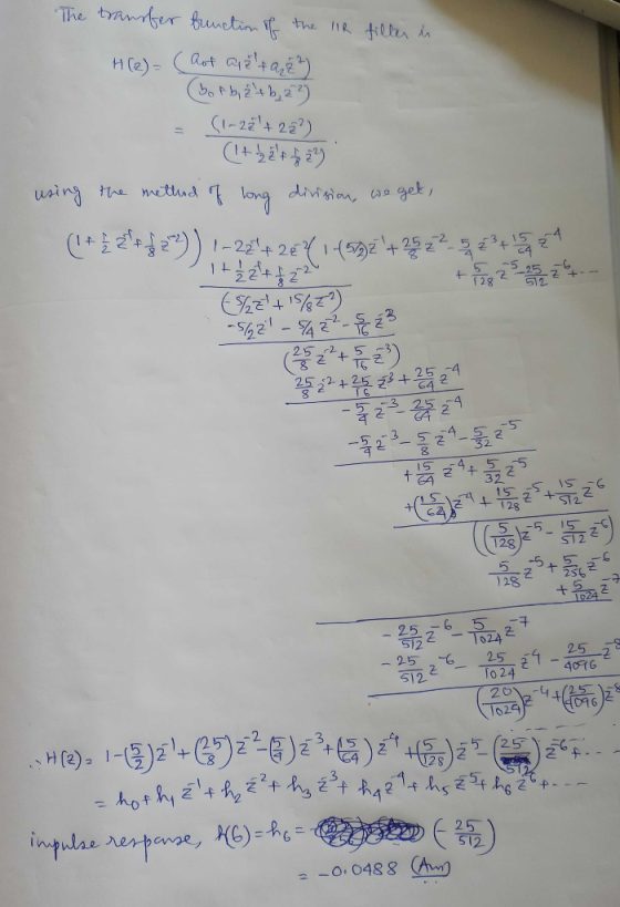
The filter coefficients of a second-order digital IIR filter are: a0 = 1, a1 = -2, a2 = 2, b0 = 1, b1 = 1/2, b2 = 1/8. (a's are numerator coefficents and b's are the denominator coefficients). Determine the value of the impulse response h(6)?
Homework Answers
Add Answer to:
The filter coefficients of a second-order digital IIR filter
are: a0 = 1, a1 = -2,...
The filter coefficients of a second-order digital IIR filter are: a0 = 1, a1 = -2,...
 The filter coefficients of a second-order digital IIR filter
are: a0 = 1, a1 = -2, a2 = 2,
b0 = 1, b1 = 1/2, b2 = 1/8. (a's
are numerator coefficients and b's are the denominator
coefficients). Determine the magnitude response (in dB) at ω =
π.
The filter coefficients of a second-order digital IR filter are: ao1, a2, a2 2, bo 1, b1- 1/2, b2- 1/8. (a's are numerator coefficients and b's are the denominator coefficients). Determine the...
The filter coefficients of a second-order digital IIR filter
are: a0 = 1, a1 = -2, a2 = 2,
b0 = 1, b1 = 1/2, b2 = 1/8. (a's
are numerator coefficients and b's are the denominator
coefficients). Determine the magnitude response (in dB) at ω =
π.
The filter coefficients of a second-order digital IR filter are: ao1, a2, a2 2, bo 1, b1- 1/2, b2- 1/8. (a's are numerator coefficients and b's are the denominator coefficients). Determine the...
1.The filter coefficients of a second-order digital IIR filter are: a0 = 1, a1 = -2,...
1.The filter coefficients of a second-order digital IIR filter are: a0 = 1, a1 = -2, a2 = 2, b0 = 1, b1 = 1/2, b2 = 1/8. (a's are numerator coefficents and b's are the denominator coefficients). Compute the magnitude response |H(ejω)| where ω = 5.174 rad/sec. 2. It is desired to extract a constant signal s(n)= s from the noisy measured signal x(n)= s(n)+v(n)= s + v(n), where v(n) is zero-mean white Gaussian noise of variance ϭv2. For...
QUESTION 28 3 points Save The Siter coefficients of a second-order digital IR filter are: ao-1,a1-2, a2-2, bo-1. b1-1/2, b2 1/8. (a's are numerator coetficients and b's are the denom...
 QUESTION 28 3 points Save The Siter coefficients of a second-order digital IR filter are: ao-1,a1-2, a2-2, bo-1. b1-1/2, b2 1/8. (a's are numerator coetficients and b's are the denominator coefficients). Determine the value of the impulse response N4? QUESTION 29 6 points Save Answer An image is to be sampled with a signal-to-quantisation ratio of at least 55 dB. The image samples are non-negative. The image sample values fall within the range from 0 to 1. How many bits...
QUESTION 6 Зро Design a second-order IIR digital low-pass filter using Butterworth approximation....
 QUESTION 6 Зро Design a second-order IIR digital low-pass filter using Butterworth approximation. Use the bilinear transformation to convert the analogue fiter to a digital one (choose the sampling period T- 2 s and the cut-off frequency as 1 rad/'s). Express the digital transfer function of the filter H(z) as: In the box below, provide the numerical answer for b1. [Note: Don't normalise the transfer func on, i.e. b0 # 1). r98111acontentid1837836_1&step QUESTION 7 Windowing based FIR filter design techniques...
Lİde-7981 1 1-1 &content-id~-1837836-1 &stepenu QUESTION 17 4 poin It is desired to extract a constant signal sío- s from the noisy measured signal kin- stowostvo.where vin) is zero-...
 Lİde-7981 1 1-1 &content-id~-1837836-1 &stepenu QUESTION 17 4 poin It is desired to extract a constant signal sío- s from the noisy measured signal kin- stowostvo.where vin) is zero- mean white Gaussian noise of variance ov. For that purpose. the following IIR lowpass fiter is used where a and b are arbitrary constants (0 < a < 1). Estimate the value of the cut-off frequency wcif a -0.8. QUESTION 18 3 poi The filter coefficients of a second-order digital IR...
QUESTION 1 Characterise the following systems as being either causal on anticausal: yn)-ePyn-1)+u...
 QUESTION 1 Characterise the following systems as being either causal on anticausal: yn)-ePyn-1)+u/n), where u/h) is the unit step and B is an arbitrary constant (B>0), Take y-1)-0. Answer with either causal or 'anticausal only QUESTION 2 For the following system: yn) -yn-1Va -x(n), for a 0.9, find y(10), assuming y(n) - o, for ns -1.Hint: find a closed form for yin) and use it to find the required output sample. (xin)-1 for n>-0) QUESTION 3 A filter has the...
Using filterDesigner in MATLAB, design a second order low pass IIR Butterworth filter whose sampling frequency (Fs) is 1...
Using filterDesigner in MATLAB, design a second order low pass IIR Butterworth filter whose sampling frequency (Fs) is 1 kHz and cutoff frequency (Fc) is 10 Hz. Find the numerator and denominator coefficients. Write its transfer function H(z) = Y(z) / X(z). Write its difference function y(k). Draw (copy from Filter Designer) the magnitude response plot. Draw (copy from Filter Designer) the phase response plot. Draw (copy from Filter Designer) the impulse response plot.
Using filterDesigner in MATLAB, design a second order low pass IIR Butterworth filter whose sampling frequency...
Using filterDesigner in MATLAB, design a second order low pass IIR Butterworth filter whose sampling frequency (Fs) is 1 kHz and cutoff frequency (Fc) is 10 Hz. Find the numerator and denominator coefficients. Write its transfer function H(z) = Y(z) / X(z). Write its difference function y(k). Draw (copy from Filter Designer) the magnitude response plot. Draw (copy from Filter Designer) the phase response plot. Draw (copy from Filter Designer) the impulse response plot.
Discrete Time Signal Processing Question 1. Consider an IIR filter A(1-2-1 cos ω0) 1-2cos ω02-1+2...
 Discrete Time Signal Processing Question 1. Consider an IIR filter A(1-2-1 cos ω0) 1-2cos ω02-1+2 I. Compute its impulse response using the difference equation with an impulse signal δ(n) as the input. Use trigonometric identities to simplify the result as much as you can 2. Draw the diagram showing the implementation of this filter in terms of adders, delays and multipliers Note: The IIR filter above generates a cosinusoidal signal when an impulse signal is applied at its input.] Question...
Design a second order IIR Butterworth low pass digital filter with a cutoff frequency of 500...
Design a second order IIR Butterworth low pass digital filter with a cutoff frequency of 500 Hz and a sampling frequency of 10,000 Hz using bilinear transformation then find the following: The output (response) due to the following inputs: Sinusoidal signal with a frequency of 100Hz. Sinusoidal signal with a frequency of 500Hz. Sinusoidal signal with a frequency of 2000Hz. Repeat (a) above for a 6thorder Butterworth filter
 The filter coefficients of a second-order digital IIR filter
are: a0 = 1, a1 = -2, a2 = 2,
b0 = 1, b1 = 1/2, b2 = 1/8. (a's
are numerator coefficients and b's are the denominator
coefficients). Determine the magnitude response (in dB) at ω =
π.
The filter coefficients of a second-order digital IR filter are: ao1, a2, a2 2, bo 1, b1- 1/2, b2- 1/8. (a's are numerator coefficients and b's are the denominator coefficients). Determine the...
The filter coefficients of a second-order digital IIR filter
are: a0 = 1, a1 = -2, a2 = 2,
b0 = 1, b1 = 1/2, b2 = 1/8. (a's
are numerator coefficients and b's are the denominator
coefficients). Determine the magnitude response (in dB) at ω =
π.
The filter coefficients of a second-order digital IR filter are: ao1, a2, a2 2, bo 1, b1- 1/2, b2- 1/8. (a's are numerator coefficients and b's are the denominator coefficients). Determine the...
 QUESTION 28 3 points Save The Siter coefficients of a second-order digital IR filter are: ao-1,a1-2, a2-2, bo-1. b1-1/2, b2 1/8. (a's are numerator coetficients and b's are the denominator coefficients). Determine the value of the impulse response N4? QUESTION 29 6 points Save Answer An image is to be sampled with a signal-to-quantisation ratio of at least 55 dB. The image samples are non-negative. The image sample values fall within the range from 0 to 1. How many bits...
 QUESTION 6 Зро Design a second-order IIR digital low-pass filter using Butterworth approximation. Use the bilinear transformation to convert the analogue fiter to a digital one (choose the sampling period T- 2 s and the cut-off frequency as 1 rad/'s). Express the digital transfer function of the filter H(z) as: In the box below, provide the numerical answer for b1. [Note: Don't normalise the transfer func on, i.e. b0 # 1). r98111acontentid1837836_1&step QUESTION 7 Windowing based FIR filter design techniques...
 Lİde-7981 1 1-1 &content-id~-1837836-1 &stepenu QUESTION 17 4 poin It is desired to extract a constant signal sío- s from the noisy measured signal kin- stowostvo.where vin) is zero- mean white Gaussian noise of variance ov. For that purpose. the following IIR lowpass fiter is used where a and b are arbitrary constants (0 < a < 1). Estimate the value of the cut-off frequency wcif a -0.8. QUESTION 18 3 poi The filter coefficients of a second-order digital IR...
 QUESTION 1 Characterise the following systems as being either causal on anticausal: yn)-ePyn-1)+u/n), where u/h) is the unit step and B is an arbitrary constant (B>0), Take y-1)-0. Answer with either causal or 'anticausal only QUESTION 2 For the following system: yn) -yn-1Va -x(n), for a 0.9, find y(10), assuming y(n) - o, for ns -1.Hint: find a closed form for yin) and use it to find the required output sample. (xin)-1 for n>-0) QUESTION 3 A filter has the...
 Discrete Time Signal Processing Question 1. Consider an IIR filter A(1-2-1 cos ω0) 1-2cos ω02-1+2 I. Compute its impulse response using the difference equation with an impulse signal δ(n) as the input. Use trigonometric identities to simplify the result as much as you can 2. Draw the diagram showing the implementation of this filter in terms of adders, delays and multipliers Note: The IIR filter above generates a cosinusoidal signal when an impulse signal is applied at its input.] Question...
Most questions answered within 3 hours.
-
284 mL of a 0.52 M potassium hydroxide solution is added to 467
mL of a...
asked 6 minutes ago -
exercise on VSEPR and molecular structrue.
octahedral
SeCl62-
TeCl62-
ClF62-
distorted
SeF62–
IF6–
asked 7 minutes ago -
Little’s Law: Val d’Costa is a world famous ski village in the
French Alps. Because of...
asked 1 hour ago -
Find the absolute error D for the calculation if A + B/C=D A=
9.4 +/- 0.4...
asked 1 hour ago -
New Air Heating and Cooling, manufactures furnaces and central
air units. The company pride itself on...
asked 1 hour ago -
A coach uses a new technique to train gymnasts. Seven
gymnasts were randomly selected and their...
asked 3 hours ago -
While rotating the tires on your car you notice a rock [mass =
0.1 Kg] stuck...
asked 5 hours ago -
Using MARS simulator, write MIPS programs according to
the following scenarios: Receive a positive integer number...
asked 7 hours ago -
An object in front of a concave mirror has a real image that is
11.5 cm...
asked 7 hours ago -
Consider the reaction, C3 H8 + O2 --> CO2 + H2O. How many
moles of O2...
asked 9 hours ago -
You and your opponent both roll a fair die. If you both roll the
same number,...
asked 9 hours ago -
In a study of the accuracy of fast food drive-through orders,
Restaurant A had 257 accurate...
asked 9 hours ago