Using filterDesigner in MATLAB, design a second order low pass IIR Butterworth filter whose sampling frequency (Fs) is 1...
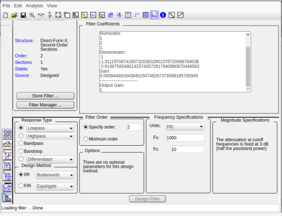
Using filterDesigner in MATLAB, design a second order low pass IIR Butterworth filter whose sampling frequency (Fs) is 1 kHz and cutoff frequency (Fc) is 10 Hz.
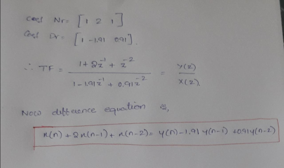
Find the numerator and denominator coefficients.
Write its transfer function H(z) = Y(z) / X(z).
Write its difference function y(k).
Draw (copy from Filter Designer) the magnitude response plot.
Draw (copy from Filter Designer) the phase response plot.
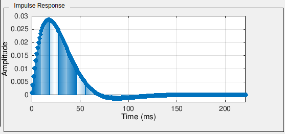
Draw (copy from Filter Designer) the impulse response plot.
Homework Answers


Thanks
Add Answer to:
Using filterDesigner in MATLAB, design a second order low pass IIR Butterworth filter whose sampling frequency (Fs) is 1...
Using filterDesigner in MATLAB, design a second order low pass IIR Butterworth filter whose sampling frequency...
Using filterDesigner in MATLAB, design a second order low pass IIR Butterworth filter whose sampling frequency (Fs) is 1 kHz and cutoff frequency (Fc) is 10 Hz. Find the numerator and denominator coefficients. Write its transfer function H(z) = Y(z) / X(z). Write its difference function y(k). Draw (copy from Filter Designer) the magnitude response plot. Draw (copy from Filter Designer) the phase response plot. Draw (copy from Filter Designer) the impulse response plot.
Design a second order IIR Butterworth low pass digital filter with a cutoff frequency of 500...
Design a second order IIR Butterworth low pass digital filter with a cutoff frequency of 500 Hz and a sampling frequency of 10,000 Hz using bilinear transformation then find the following: The output (response) due to the following inputs: Sinusoidal signal with a frequency of 100Hz. Sinusoidal signal with a frequency of 500Hz. Sinusoidal signal with a frequency of 2000Hz. Repeat (a) above for a 6thorder Butterworth filter
QUESTION 6 Зро Design a second-order IIR digital low-pass filter using Butterworth approximation....
 QUESTION 6 Зро Design a second-order IIR digital low-pass filter using Butterworth approximation. Use the bilinear transformation to convert the analogue fiter to a digital one (choose the sampling period T- 2 s and the cut-off frequency as 1 rad/'s). Express the digital transfer function of the filter H(z) as: In the box below, provide the numerical answer for b1. [Note: Don't normalise the transfer func on, i.e. b0 # 1). r98111acontentid1837836_1&step QUESTION 7 Windowing based FIR filter design techniques...
Discrete Time Signal Processing Question 1. Consider an IIR filter A(1-2-1 cos ω0) 1-2cos ω02-1+2...
 Discrete Time Signal Processing Question 1. Consider an IIR filter A(1-2-1 cos ω0) 1-2cos ω02-1+2 I. Compute its impulse response using the difference equation with an impulse signal δ(n) as the input. Use trigonometric identities to simplify the result as much as you can 2. Draw the diagram showing the implementation of this filter in terms of adders, delays and multipliers Note: The IIR filter above generates a cosinusoidal signal when an impulse signal is applied at its input.] Question...
1. By using an analog filter with a Butterworth response of order 3, design a digital IIR low pass filter with 3-db cutoff frequency 2c 0.6TT a) b) c) Evaluate the transfer function of the analog fil...
 1. By using an analog filter with a Butterworth response of order 3, design a digital IIR low pass filter with 3-db cutoff frequency 2c 0.6TT a) b) c) Evaluate the transfer function of the analog filter (10marks) Skecth the block diagram of transfer function (5 marks) Plot the magnitude response of the filters. (5marks)
1. By using an analog filter with a Butterworth response of order 3, design a digital IIR low pass filter with 3-db cutoff frequency 2c...
1. By using an analog filter with a Butterworth response of order 3, design a digital IIR low pass filter with 3-db cutoff frequency 2c 0.6TT a) b) c) Evaluate the transfer function of the analog filter (10marks) Skecth the block diagram of transfer function (5 marks) Plot the magnitude response of the filters. (5marks)
1. By using an analog filter with a Butterworth response of order 3, design a digital IIR low pass filter with 3-db cutoff frequency 2c...
Design a fourth order low pass Butterworth filter with a cutoff frequency of 2 kHz and...
Design a fourth order low pass Butterworth filter with a cutoff frequency of 2 kHz and draw the frequency response for the filter.
Design lowpass IIR filter with the following specifications: Filter order = 2, Butterworth type C...
Design lowpass IIR filter with the following specifications: Filter order = 2, Butterworth type Cut-off frequency=800 Hz Sampling rate =8000 Hz Design using the bilinear z-transform design method Print the lowpass IIR filter coefficients and plot the frequency responses using MATLAB. MATLAB>>freqz(bLP,aLP,512,8000); axis([0 4000 –40 1]); Label and print your graph. What is the filter gain at the cut-off frequency 800 Hz? What are the filter gains for the stopband at 2000 Hz and the passband at 50 Hz based...
MUST BE IN MATLAB Design a low pass filter for this signal. Set the pass band...
MUST BE IN MATLAB Design a low pass filter for this signal. Set the pass band frequency to 4.9 GHz and the stop band frequency to 5.6 GHz. Allow for 1 dB of attenuation in the pass band and require at least 20 dB of attenuation in the stop band. a. First design a Butterworth filter. Use the command buttord() to determine the order and the normalizing frequency for the filter. Use [Num,Den]=butter() to determine the numerator and denominator coefficients...
Design a low-pass Butterworth filter of the lowest order possible that has a cutoff frequency of ...
Design a low-pass Butterworth filter of the lowest order possible that has a cutoff frequency of 100 kHz and a no more then -30 dB at 600kHz. Use as many 50Ω resistors as possible. Draw the circuit.
please need correct answer. I will upvote. Design a second-order digital bandpass Butterworth filter with a...
please need correct answer. I will upvote. Design a second-order digital bandpass Butterworth filter with a lower cutoff frequency of 1.9 kHz, an upper cutoff frequency 2.1 kHz, and a passband ripple of 3dB at a sampling frequency of 8,000 Hz. a. Determine the transfer function and difference equation. b. Use MATLAB to plot the magnitude and phase frequency respon
 QUESTION 6 Зро Design a second-order IIR digital low-pass filter using Butterworth approximation. Use the bilinear transformation to convert the analogue fiter to a digital one (choose the sampling period T- 2 s and the cut-off frequency as 1 rad/'s). Express the digital transfer function of the filter H(z) as: In the box below, provide the numerical answer for b1. [Note: Don't normalise the transfer func on, i.e. b0 # 1). r98111acontentid1837836_1&step QUESTION 7 Windowing based FIR filter design techniques...
 Discrete Time Signal Processing Question 1. Consider an IIR filter A(1-2-1 cos ω0) 1-2cos ω02-1+2 I. Compute its impulse response using the difference equation with an impulse signal δ(n) as the input. Use trigonometric identities to simplify the result as much as you can 2. Draw the diagram showing the implementation of this filter in terms of adders, delays and multipliers Note: The IIR filter above generates a cosinusoidal signal when an impulse signal is applied at its input.] Question...
 1. By using an analog filter with a Butterworth response of order 3, design a digital IIR low pass filter with 3-db cutoff frequency 2c 0.6TT a) b) c) Evaluate the transfer function of the analog filter (10marks) Skecth the block diagram of transfer function (5 marks) Plot the magnitude response of the filters. (5marks)
1. By using an analog filter with a Butterworth response of order 3, design a digital IIR low pass filter with 3-db cutoff frequency 2c...
1. By using an analog filter with a Butterworth response of order 3, design a digital IIR low pass filter with 3-db cutoff frequency 2c 0.6TT a) b) c) Evaluate the transfer function of the analog filter (10marks) Skecth the block diagram of transfer function (5 marks) Plot the magnitude response of the filters. (5marks)
1. By using an analog filter with a Butterworth response of order 3, design a digital IIR low pass filter with 3-db cutoff frequency 2c...
Most questions answered within 3 hours.
-
A solid, frictionless cylindrical reel of mass M=5.00kg and
radius R=0.55m is used to draw water...
asked 1 minute ago -
how do radio waves get emitted from Jupiter?
- do they come from radiation from planet...
asked 1 minute ago -
The test statistic used in the F test for the equality of two
variances is calculated...
asked 13 minutes ago -
How does neutralisation of IL-6 trans-signaling affect the
autoimmune disease and inflammation? What if the trans-signaling...
asked 3 minutes ago -
f an allele is 'fixed' in a population, what is its
frequency?
0.50
0.75
0.25
0...
asked 17 minutes ago -
Do we have a duty of national loyalty in business? What is the
major argument in...
asked 18 minutes ago -
compare the international treatment of segment reporting to the
us gaap treatment
asked 14 minutes ago -
A statistics student finds herself struggling with a newspaper
article stating that only eighteen percent of...
asked 48 minutes ago -
People with beriberi, a disease caused by a thiamin deficiency,
have elevated levels of blood pyruvate...
asked 34 minutes ago -
PYTHON Programming Exercise 2: Create a Simple Cost Calculator
Write a program that displays input fields...
asked 40 minutes ago -
1.Seki agreed that Groupon could sell 18 hot air
balloon rides on his Magical Adventures company...
asked 41 minutes ago -
A cohort study is conducted to determine whether smoking is
associated with an increased risk of...
asked 47 minutes ago