Design lowpass IIR filter with the following specifications: Filter order = 2, Butterworth type C...
Design lowpass IIR filter with the following specifications: Filter order = 2, Butterworth type Cut-off frequency=800 Hz Sampling rate =8000 Hz Design using the bilinear z-transform design method
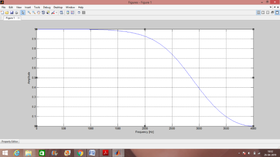
Print the lowpass IIR filter coefficients and plot the frequency responses using MATLAB. MATLAB>>freqz(bLP,aLP,512,8000); axis([0 4000 –40 1]);
Label and print your graph. What is the filter gain at the cut-off frequency 800 Hz? What are the filter gains for the stopband at 2000 Hz and the passband at 50 Hz based on the plot of the magnitude frequency response?
Homework Answers
clc;clear all;
Fs = 8000;
atmax =3;
wp =800*2*pi;
Wp=2*atan(wp/2);
N=2;
Whp=Wp/((10^(.1*atmax)-1)^(1/(2*N)));
whp=2*atan(Whp/2);
wn=whp/pi;
[b,a]=butter(N,wn);
[H,w]=freqz(b,a,512);
fq=Fs*w/(2*pi);
mag=abs(H);
plot(fq,mag)
ylabel('Amplitude');
xlabel('Frequency [Hz]'); grid
filter coefficients:
a =
1.0000 0.5169 0.2192
>> b
b =
0.4340 0.8681 0.4340
Add Answer to:
Design lowpass IIR filter with the following specifications: Filter order = 2, Butterworth type C...
An IIR low-pass filter is to be designed to meet the following specifications:
An IIR low-pass filter is to be designed to meet the following specifications: 1. Passband cutoff frequency of 0.22 π with a passband ripple less than 0.01.2. Stopband cutoff frequency of 0.24 π with a stopband attenuation greater than 40 dB.(i) Determine the filter order required to meet these specifications if a digital butterworth filter is designed using the bilinear transformation. (ii) Determine the filter order required to meet these specifications if a digital chebyshev filter is designed using the bilinear transformation.
NI+N2-1. Find the output y(n) by using the DFT and the inverse DFT method. 4. (20 points) Design a lowpass Butterworth filter with the following specifications: A desired peak passband ripple Rp...
 NI+N2-1. Find the output y(n) by using the DFT and the inverse DFT method. 4. (20 points) Design a lowpass Butterworth filter with the following specifications: A desired peak passband ripple Rp of 2 dB, the minimum stopband attenuation R, of 60 dB, the passband edge frequency op of 1000 rad/sec, and stopband edge frequency os of 3000 rad/sec (1) Estimate the order for this filter (2) Estimate the cut-off frequency for this filter. 5. (20 points) Consider the first-order...
2. Design a digital lowpass filter to meet the following specifications: passband edge = 0.45π stopband...
2. Design a digital lowpass filter to meet the following specifications: passband edge = 0.45π stopband edge = 0.5π Rp = 0.5 dB, As = 60 dB a. Design a Buttterworth filter, you may use the butterord and butter commands to implement. b. Design Chebyshev Type 1 filter ( use the equivalent commands to above ) c. Design an Elliptic fitler ( use the equivalent commands to part a ). d. List the order of each filter and find the...
6. (20 points) (1) Design an analog lowpass filter with a cut-off frequency of 9 rad/sec by starting with an analogue prototype first-order lowpass filter with cut-off frequency of 1 rad/sec. Sho...
 6. (20 points) (1) Design an analog lowpass filter with a cut-off frequency of 9 rad/sec by starting with an analogue prototype first-order lowpass filter with cut-off frequency of 1 rad/sec. Show the system transfer function H(s) (2) Design an IIR digital filter Hz) that corresponds to the above H(s) by using the bilinear transform method without prewarping with T 0.1 second. Show the system transfer function Hz) and find its corresponding digital cut-off frequency Be approximately (3) What is...
Design a second order IIR Butterworth low pass digital filter with a cutoff frequency of 500...
Design a second order IIR Butterworth low pass digital filter with a cutoff frequency of 500 Hz and a sampling frequency of 10,000 Hz using bilinear transformation then find the following: The output (response) due to the following inputs: Sinusoidal signal with a frequency of 100Hz. Sinusoidal signal with a frequency of 500Hz. Sinusoidal signal with a frequency of 2000Hz. Repeat (a) above for a 6thorder Butterworth filter
Use Bilinear Transform to design a lowpass Butterworth digital filter that passes frequencies up ...
Use Bilinear Transform to design a lowpass Butterworth digital filter that passes frequencies up to f=1500Hz with minimum gain -7dB. The filter is to block frequencies from f = 3600Hz with a maximum gain-38dB. The sampling frequency is f = 8000 a) Find the Butterworth Filter Order = (N), 3-dB Cutoff frequency, and the numerator and denominator coefficients of the H(z) b) Which of the frequencies in the followingx()will be passed by your designed filter?x(t) = cos(1600πt)+5cos(8000πt)+3cos(2300πt)+ 2cos(1400πt)
A digital low pass IIR filter is to be designed with Butterworth approximation using the Bilinear transformation
A digital low pass IIR filter is to be designed with Butterworth approximation using the Bilinear transformation technique having the following specifications:(i) Passband magnitude is constant within 1 dB for frequencies below 0.2 π.(ii) Stopband attenuation is greater than 15 dB for frequencies between 0.3 π to π. Determine the order of the filter, cutoff frequency, poles location and transfer function of digital filter in order to meet the above specifications.
1. Design a 10th-order lowpass FIR filter using the window method (fir1) to cut frequencies above...
1. Design a 10th-order lowpass FIR filter using the window method (fir1) to cut frequencies above 30Hz in an application where the sampling frequency is 125 Hz. 2. Plot the filter coefficients that define the filter (stem). 3. Plot the frequency response of the FIR filter designed (freqz) 4. Design a 100th-order lowpass FIR filter using the window method (fir1) to cut frequencies above 30Hz in an application where the sampling frequency is 125 Hz. Plot the filter coefficients that...
Consider an FIR lowpass filter design with the following specifications: Passband Stopband Passband ripple Stopband attenuation...
 Consider an FIR lowpass filter design with the following
specifications:
Passband
Stopband
Passband ripple
Stopband attenuation
Sampling rate
Determine the following:
a. window method
b. length of the FIR filter
c. cutoff frequency for the design equation
We were unable to transcribe this imageWe were unable to transcribe this image= 1200 4000H = 0.1dB We were unable to transcribe this imageWe were unable to transcribe this image
Consider an FIR lowpass filter design with the following
specifications:
Passband
Stopband
Passband ripple
Stopband attenuation
Sampling rate
Determine the following:
a. window method
b. length of the FIR filter
c. cutoff frequency for the design equation
We were unable to transcribe this imageWe were unable to transcribe this image= 1200 4000H = 0.1dB We were unable to transcribe this imageWe were unable to transcribe this image
Using filterDesigner in MATLAB, design a second order low pass IIR Butterworth filter whose sampling frequency...
Using filterDesigner in MATLAB, design a second order low pass IIR Butterworth filter whose sampling frequency (Fs) is 1 kHz and cutoff frequency (Fc) is 10 Hz. Find the numerator and denominator coefficients. Write its transfer function H(z) = Y(z) / X(z). Write its difference function y(k). Draw (copy from Filter Designer) the magnitude response plot. Draw (copy from Filter Designer) the phase response plot. Draw (copy from Filter Designer) the impulse response plot.
 NI+N2-1. Find the output y(n) by using the DFT and the inverse DFT method. 4. (20 points) Design a lowpass Butterworth filter with the following specifications: A desired peak passband ripple Rp of 2 dB, the minimum stopband attenuation R, of 60 dB, the passband edge frequency op of 1000 rad/sec, and stopband edge frequency os of 3000 rad/sec (1) Estimate the order for this filter (2) Estimate the cut-off frequency for this filter. 5. (20 points) Consider the first-order...
 6. (20 points) (1) Design an analog lowpass filter with a cut-off frequency of 9 rad/sec by starting with an analogue prototype first-order lowpass filter with cut-off frequency of 1 rad/sec. Show the system transfer function H(s) (2) Design an IIR digital filter Hz) that corresponds to the above H(s) by using the bilinear transform method without prewarping with T 0.1 second. Show the system transfer function Hz) and find its corresponding digital cut-off frequency Be approximately (3) What is...
 Consider an FIR lowpass filter design with the following
specifications:
Passband
Stopband
Passband ripple
Stopband attenuation
Sampling rate
Determine the following:
a. window method
b. length of the FIR filter
c. cutoff frequency for the design equation
We were unable to transcribe this imageWe were unable to transcribe this image= 1200 4000H = 0.1dB We were unable to transcribe this imageWe were unable to transcribe this image
Consider an FIR lowpass filter design with the following
specifications:
Passband
Stopband
Passband ripple
Stopband attenuation
Sampling rate
Determine the following:
a. window method
b. length of the FIR filter
c. cutoff frequency for the design equation
We were unable to transcribe this imageWe were unable to transcribe this image= 1200 4000H = 0.1dB We were unable to transcribe this imageWe were unable to transcribe this image
Most questions answered within 3 hours.
-
Complete the following reactions which form ethers (A
and B) and cyclic ethers (C-E) as major...
asked 1 minute ago -
in a perfectly elastic collision what is the velocity of ball A
if the original direction...
asked 30 minutes ago -
PLEASE ANSWER ALL
1) The pressure of the atmosphere decreases with increasing
altitude in the
Choose...
asked 44 minutes ago -
A simple random sample of 25,000 individuals are surveyed in
order to determine the prevalence of...
asked 46 minutes ago -
People who do very detailed work close up, such as jewelers,
often can see objects clearly...
asked 49 minutes ago -
14 years ago, Blue Lake Corp. issued 30 year to maturity
zero-coupon bonds with a par...
asked 41 minutes ago -
Warnerwoods Company uses a perpetual inventory system. It
entered into the following purchases and sales transactions...
asked 37 minutes ago -
Equivalent Units of Conversion Costs
The Rolling Department of Oak Ridge Steel Company had 6,842 tons...
asked 42 minutes ago -
what does the concept of "core competence" mean? why
is this concept important? How would you...
asked 45 minutes ago -
__________ is a type of visualization that is linked to strategy
and used within a formal...
asked 45 minutes ago -
A national magazine stated that at most,12% of millennials
have a pool membership. Formulate an appropriate...
asked 57 minutes ago -
Can
you provide the mechanism for enamine hydrolysis. Any example will
work, thank you.
asked 1 hour ago