
Homework Answers

Add Answer to:
6. (20 points) (1) Design an analog lowpass filter with a cut-off frequency of 9 rad/sec by starting with an analogue prototype first-order lowpass filter with cut-off frequency of 1 rad/sec. Sho...
Design lowpass IIR filter with the following specifications: Filter order = 2, Butterworth type C...
Design lowpass IIR filter with the following specifications: Filter order = 2, Butterworth type Cut-off frequency=800 Hz Sampling rate =8000 Hz Design using the bilinear z-transform design method Print the lowpass IIR filter coefficients and plot the frequency responses using MATLAB. MATLAB>>freqz(bLP,aLP,512,8000); axis([0 4000 –40 1]); Label and print your graph. What is the filter gain at the cut-off frequency 800 Hz? What are the filter gains for the stopband at 2000 Hz and the passband at 50 Hz based...
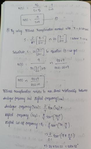
1.(10pts) A first-order highpass filter whose transfer function is represented in Laplace transforms as H HPS) -, where Ωο(cut-off frequency) is 1000 rad/sec. Convert this analog filter into a digita...
 1.(10pts) A first-order highpass filter whose transfer function is represented in Laplace transforms as H HPS) -, where Ωο(cut-off frequency) is 1000 rad/sec. Convert this analog filter into a digital filter with bilinear-transformation assuming sampling rate is 2500Hz and then determine its input-output relation. In your answer, you will need to provide (i) HHP) and ii) filter's input-output relation. You can find the formula of bilinear transformation in either lecture notes (Lec 14) or textbook pp.494
1.(10pts) A first-order highpass...
1.(10pts) A first-order highpass filter whose transfer function is represented in Laplace transforms as H HPS) -, where Ωο(cut-off frequency) is 1000 rad/sec. Convert this analog filter into a digital filter with bilinear-transformation assuming sampling rate is 2500Hz and then determine its input-output relation. In your answer, you will need to provide (i) HHP) and ii) filter's input-output relation. You can find the formula of bilinear transformation in either lecture notes (Lec 14) or textbook pp.494
1.(10pts) A first-order highpass...
4. We wish to design a digital bandpass filter from a second-order analog lowpass Butterworth filter...
 4. We wish to design a digital bandpass filter from a second-order analog lowpass Butterworth filter prototype using the bilinear transformation. The cutoff frequencies (measured at the half-power points) for the digital filter should lie at ω 5t/12 and ω-7t/12. The analog prototype is given by 1 s2+/2s+1 with the half-power point at 2 Determine the system function for the digital bandpass filter. a) b) Make the transfer from LPF to BPF in the analog domain Make the transfer from...
2. (50 marks) Consider using the impulse invariance method to design a prototype IIR digital filter...
 2. (50 marks) Consider using the impulse invariance method to design a prototype IIR digital filter corresponding to the analogue prototype filter: He(s) = 52 +58 +6 a) Write the correct sequence of basic steps involved in this method. b) Determine the transfer function H(z) of the resulting digital filter. Simplify H(2) as much as possible. Assume a sampling frequency of fs = 100 HZ.
QUESTION 6 Зро Design a second-order IIR digital low-pass filter using Butterworth approximation....
 QUESTION 6 Зро Design a second-order IIR digital low-pass filter using Butterworth approximation. Use the bilinear transformation to convert the analogue fiter to a digital one (choose the sampling period T- 2 s and the cut-off frequency as 1 rad/'s). Express the digital transfer function of the filter H(z) as: In the box below, provide the numerical answer for b1. [Note: Don't normalise the transfer func on, i.e. b0 # 1). r98111acontentid1837836_1&step QUESTION 7 Windowing based FIR filter design techniques...
NI+N2-1. Find the output y(n) by using the DFT and the inverse DFT method. 4. (20 points) Design a lowpass Butterworth filter with the following specifications: A desired peak passband ripple Rp...
 NI+N2-1. Find the output y(n) by using the DFT and the inverse DFT method. 4. (20 points) Design a lowpass Butterworth filter with the following specifications: A desired peak passband ripple Rp of 2 dB, the minimum stopband attenuation R, of 60 dB, the passband edge frequency op of 1000 rad/sec, and stopband edge frequency os of 3000 rad/sec (1) Estimate the order for this filter (2) Estimate the cut-off frequency for this filter. 5. (20 points) Consider the first-order...
4. (20 points) An ideal analog integrator is described by the system function: H(s) 1) Design...
 4. (20 points) An ideal analog integrator is described by the system function: H(s) 1) Design a discrete-time "integrator" using the bilinear transformation with Ts 2 sec. t is the difference equation relating xin) to yin) thint: divide top and bottom of H(Z) by ) 3) Determine the unit sample (impulse) response of the digital fite. 4) Assuming a sampling frequency of 0.5 Hz, use the impulse invariance method to find an approximation for Hz). Hint: Inverse Laplace Transform of...
1. By using an analog filter with a Butterworth response of order 3, design a digital IIR low pass filter with 3-db cutoff frequency 2c 0.6TT a) b) c) Evaluate the transfer function of the analog fil...
 1. By using an analog filter with a Butterworth response of order 3, design a digital IIR low pass filter with 3-db cutoff frequency 2c 0.6TT a) b) c) Evaluate the transfer function of the analog filter (10marks) Skecth the block diagram of transfer function (5 marks) Plot the magnitude response of the filters. (5marks)
1. By using an analog filter with a Butterworth response of order 3, design a digital IIR low pass filter with 3-db cutoff frequency 2c...
1. By using an analog filter with a Butterworth response of order 3, design a digital IIR low pass filter with 3-db cutoff frequency 2c 0.6TT a) b) c) Evaluate the transfer function of the analog filter (10marks) Skecth the block diagram of transfer function (5 marks) Plot the magnitude response of the filters. (5marks)
1. By using an analog filter with a Butterworth response of order 3, design a digital IIR low pass filter with 3-db cutoff frequency 2c...
1. Design a 10th-order lowpass FIR filter using the window method (fir1) to cut frequencies above...
1. Design a 10th-order lowpass FIR filter using the window method (fir1) to cut frequencies above 30Hz in an application where the sampling frequency is 125 Hz. 2. Plot the filter coefficients that define the filter (stem). 3. Plot the frequency response of the FIR filter designed (freqz) 4. Design a 100th-order lowpass FIR filter using the window method (fir1) to cut frequencies above 30Hz in an application where the sampling frequency is 125 Hz. Plot the filter coefficients that...
QUESTION 28 3 points Save The Siter coefficients of a second-order digital IR filter are: ao-1,a1-2, a2-2, bo-1. b1-1/2, b2 1/8. (a's are numerator coetficients and b's are the denom...
 QUESTION 28 3 points Save The Siter coefficients of a second-order digital IR filter are: ao-1,a1-2, a2-2, bo-1. b1-1/2, b2 1/8. (a's are numerator coetficients and b's are the denominator coefficients). Determine the value of the impulse response N4? QUESTION 29 6 points Save Answer An image is to be sampled with a signal-to-quantisation ratio of at least 55 dB. The image samples are non-negative. The image sample values fall within the range from 0 to 1. How many bits...
 1.(10pts) A first-order highpass filter whose transfer function is represented in Laplace transforms as H HPS) -, where Ωο(cut-off frequency) is 1000 rad/sec. Convert this analog filter into a digital filter with bilinear-transformation assuming sampling rate is 2500Hz and then determine its input-output relation. In your answer, you will need to provide (i) HHP) and ii) filter's input-output relation. You can find the formula of bilinear transformation in either lecture notes (Lec 14) or textbook pp.494
1.(10pts) A first-order highpass...
1.(10pts) A first-order highpass filter whose transfer function is represented in Laplace transforms as H HPS) -, where Ωο(cut-off frequency) is 1000 rad/sec. Convert this analog filter into a digital filter with bilinear-transformation assuming sampling rate is 2500Hz and then determine its input-output relation. In your answer, you will need to provide (i) HHP) and ii) filter's input-output relation. You can find the formula of bilinear transformation in either lecture notes (Lec 14) or textbook pp.494
1.(10pts) A first-order highpass...
 4. We wish to design a digital bandpass filter from a second-order analog lowpass Butterworth filter prototype using the bilinear transformation. The cutoff frequencies (measured at the half-power points) for the digital filter should lie at ω 5t/12 and ω-7t/12. The analog prototype is given by 1 s2+/2s+1 with the half-power point at 2 Determine the system function for the digital bandpass filter. a) b) Make the transfer from LPF to BPF in the analog domain Make the transfer from...
 2. (50 marks) Consider using the impulse invariance method to design a prototype IIR digital filter corresponding to the analogue prototype filter: He(s) = 52 +58 +6 a) Write the correct sequence of basic steps involved in this method. b) Determine the transfer function H(z) of the resulting digital filter. Simplify H(2) as much as possible. Assume a sampling frequency of fs = 100 HZ.
 QUESTION 6 Зро Design a second-order IIR digital low-pass filter using Butterworth approximation. Use the bilinear transformation to convert the analogue fiter to a digital one (choose the sampling period T- 2 s and the cut-off frequency as 1 rad/'s). Express the digital transfer function of the filter H(z) as: In the box below, provide the numerical answer for b1. [Note: Don't normalise the transfer func on, i.e. b0 # 1). r98111acontentid1837836_1&step QUESTION 7 Windowing based FIR filter design techniques...
 NI+N2-1. Find the output y(n) by using the DFT and the inverse DFT method. 4. (20 points) Design a lowpass Butterworth filter with the following specifications: A desired peak passband ripple Rp of 2 dB, the minimum stopband attenuation R, of 60 dB, the passband edge frequency op of 1000 rad/sec, and stopband edge frequency os of 3000 rad/sec (1) Estimate the order for this filter (2) Estimate the cut-off frequency for this filter. 5. (20 points) Consider the first-order...
 4. (20 points) An ideal analog integrator is described by the system function: H(s) 1) Design a discrete-time "integrator" using the bilinear transformation with Ts 2 sec. t is the difference equation relating xin) to yin) thint: divide top and bottom of H(Z) by ) 3) Determine the unit sample (impulse) response of the digital fite. 4) Assuming a sampling frequency of 0.5 Hz, use the impulse invariance method to find an approximation for Hz). Hint: Inverse Laplace Transform of...
 1. By using an analog filter with a Butterworth response of order 3, design a digital IIR low pass filter with 3-db cutoff frequency 2c 0.6TT a) b) c) Evaluate the transfer function of the analog filter (10marks) Skecth the block diagram of transfer function (5 marks) Plot the magnitude response of the filters. (5marks)
1. By using an analog filter with a Butterworth response of order 3, design a digital IIR low pass filter with 3-db cutoff frequency 2c...
1. By using an analog filter with a Butterworth response of order 3, design a digital IIR low pass filter with 3-db cutoff frequency 2c 0.6TT a) b) c) Evaluate the transfer function of the analog filter (10marks) Skecth the block diagram of transfer function (5 marks) Plot the magnitude response of the filters. (5marks)
1. By using an analog filter with a Butterworth response of order 3, design a digital IIR low pass filter with 3-db cutoff frequency 2c...
 QUESTION 28 3 points Save The Siter coefficients of a second-order digital IR filter are: ao-1,a1-2, a2-2, bo-1. b1-1/2, b2 1/8. (a's are numerator coetficients and b's are the denominator coefficients). Determine the value of the impulse response N4? QUESTION 29 6 points Save Answer An image is to be sampled with a signal-to-quantisation ratio of at least 55 dB. The image samples are non-negative. The image sample values fall within the range from 0 to 1. How many bits...
Most questions answered within 3 hours.
-
Find the expected count and the contribution to the chi-square
statistic for the (Group 1, No)...
asked 15 minutes ago -
Suppose you are purchasing a meal and with every meal a you
receive one of 10...
asked 6 minutes ago -
A 75.0 kg 0erson is riding in a car moving at 20.0 m/s when the
car...
asked 8 minutes ago -
What does Δp = QR mean in words?
Pushing a viscous fluid through a pipe requires...
asked 14 minutes ago -
We know that system.out.println (“object number” + n ); is
legal.String name; int n; name =...
asked 14 minutes ago -
Come up with a real-life problem (open-ended) and solve it by
designing and writing a Java...
asked 22 minutes ago -
Power Music owns five music stores, where it sells music,
instruments, and supplies. In addition, it...
asked 31 minutes ago -
True or false and
why:
Given the following sequence of numbers to be
inserted {4,5,6,1,2,3,8,7}, the...
asked 39 minutes ago -
Code using Java
What is an interface? Complete the following code:
interface IExample{
public void print();...
asked 49 minutes ago -
Bob Nale is the owner of Nale’s Quick Fill. Bob would like to
estimate the mean...
asked 1 hour ago -
what are your opinions on environmental rights and absolute bans
?
asked 1 hour ago -
benzene melts at 5.5 degrees c if the vapor pressure of liquid
benzene is 19.2 kOa...
asked 1 hour ago