
Homework Answers
Add Answer to:
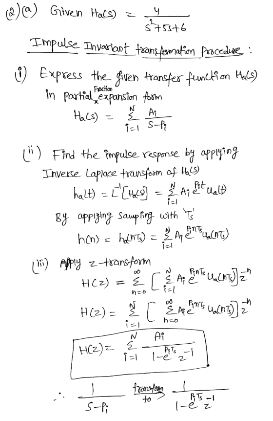
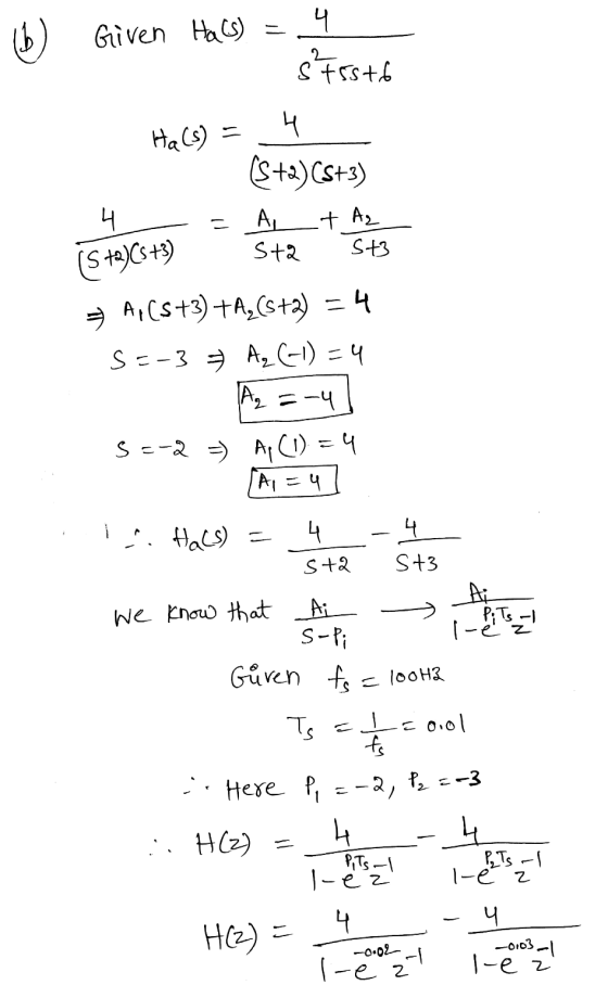
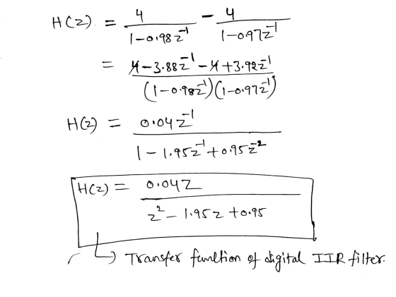
2. (50 marks) Consider using the impulse invariance method to design a prototype IIR digital filter...
6. (20 points) (1) Design an analog lowpass filter with a cut-off frequency of 9 rad/sec by starting with an analogue prototype first-order lowpass filter with cut-off frequency of 1 rad/sec. Sho...
 6. (20 points) (1) Design an analog lowpass filter with a cut-off frequency of 9 rad/sec by starting with an analogue prototype first-order lowpass filter with cut-off frequency of 1 rad/sec. Show the system transfer function H(s) (2) Design an IIR digital filter Hz) that corresponds to the above H(s) by using the bilinear transform method without prewarping with T 0.1 second. Show the system transfer function Hz) and find its corresponding digital cut-off frequency Be approximately (3) What is...
QUESTION 6 Зро Design a second-order IIR digital low-pass filter using Butterworth approximation....
 QUESTION 6 Зро Design a second-order IIR digital low-pass filter using Butterworth approximation. Use the bilinear transformation to convert the analogue fiter to a digital one (choose the sampling period T- 2 s and the cut-off frequency as 1 rad/'s). Express the digital transfer function of the filter H(z) as: In the box below, provide the numerical answer for b1. [Note: Don't normalise the transfer func on, i.e. b0 # 1). r98111acontentid1837836_1&step QUESTION 7 Windowing based FIR filter design techniques...
Using filterDesigner in MATLAB, design a second order low pass IIR Butterworth filter whose sampling frequency...
Using filterDesigner in MATLAB, design a second order low pass IIR Butterworth filter whose sampling frequency (Fs) is 1 kHz and cutoff frequency (Fc) is 10 Hz. Find the numerator and denominator coefficients. Write its transfer function H(z) = Y(z) / X(z). Write its difference function y(k). Draw (copy from Filter Designer) the magnitude response plot. Draw (copy from Filter Designer) the phase response plot. Draw (copy from Filter Designer) the impulse response plot.
Using filterDesigner in MATLAB, design a second order low pass IIR Butterworth filter whose sampling frequency (Fs) is 1...
Using filterDesigner in MATLAB, design a second order low pass IIR Butterworth filter whose sampling frequency (Fs) is 1 kHz and cutoff frequency (Fc) is 10 Hz. Find the numerator and denominator coefficients. Write its transfer function H(z) = Y(z) / X(z). Write its difference function y(k). Draw (copy from Filter Designer) the magnitude response plot. Draw (copy from Filter Designer) the phase response plot. Draw (copy from Filter Designer) the impulse response plot.
Question 2. (25 marks) Design a discrete time low-pass IIR filter operating at a sampling rate of 8 kHz such that its magnitude response is monotonic (i.e., smooth with no ripples) and satisfies the...
 Question 2. (25 marks) Design a discrete time low-pass IIR filter operating at a sampling rate of 8 kHz such that its magnitude response is monotonic (i.e., smooth with no ripples) and satisfies the following conditions (i) The magnitude response has an attenuation of at least 20dB at 2000 Hz (ii) The magnitude response has an attenuation of at most 2dB at 1000 Hz Determine the transfer function, H(z) A. 120 Marks] sketch the Direct Form II structure of the...
Design a second order IIR Butterworth low pass digital filter with a cutoff frequency of 500...
Design a second order IIR Butterworth low pass digital filter with a cutoff frequency of 500 Hz and a sampling frequency of 10,000 Hz using bilinear transformation then find the following: The output (response) due to the following inputs: Sinusoidal signal with a frequency of 100Hz. Sinusoidal signal with a frequency of 500Hz. Sinusoidal signal with a frequency of 2000Hz. Repeat (a) above for a 6thorder Butterworth filter
Design lowpass IIR filter with the following specifications: Filter order = 2, Butterworth type C...
Design lowpass IIR filter with the following specifications: Filter order = 2, Butterworth type Cut-off frequency=800 Hz Sampling rate =8000 Hz Design using the bilinear z-transform design method Print the lowpass IIR filter coefficients and plot the frequency responses using MATLAB. MATLAB>>freqz(bLP,aLP,512,8000); axis([0 4000 –40 1]); Label and print your graph. What is the filter gain at the cut-off frequency 800 Hz? What are the filter gains for the stopband at 2000 Hz and the passband at 50 Hz based...
1. By using an analog filter with a Butterworth response of order 3, design a digital IIR low pass filter with 3-db cutoff frequency 2c 0.6TT a) b) c) Evaluate the transfer function of the analog fil...
 1. By using an analog filter with a Butterworth response of order 3, design a digital IIR low pass filter with 3-db cutoff frequency 2c 0.6TT a) b) c) Evaluate the transfer function of the analog filter (10marks) Skecth the block diagram of transfer function (5 marks) Plot the magnitude response of the filters. (5marks)
1. By using an analog filter with a Butterworth response of order 3, design a digital IIR low pass filter with 3-db cutoff frequency 2c...
1. By using an analog filter with a Butterworth response of order 3, design a digital IIR low pass filter with 3-db cutoff frequency 2c 0.6TT a) b) c) Evaluate the transfer function of the analog filter (10marks) Skecth the block diagram of transfer function (5 marks) Plot the magnitude response of the filters. (5marks)
1. By using an analog filter with a Butterworth response of order 3, design a digital IIR low pass filter with 3-db cutoff frequency 2c...
Please solve these questions. Thank you. 16.3 (a) Use the impulse invariance method to show that...
 Please solve these questions. Thank you.
16.3 (a) Use the impulse invariance method to show that the analog transfer function given by 2.6702 H(s)=3+2.7747s2 +3.8494s +2.6702 B. Friedlander and B. Porat, the modified Yule-Walker method of ARMA spectral estimation, IEEE Transactions on Aerospace Electronic Systems (1984), AES-20(2), 158-173. (2] L. B. Jackson, Digital Filters and Signal Processing. 3rd edn. Kluwer Academic Publishers (1996), Chap. 10, pp. 345-355 16 lIR filter design results in the following z-transfer function: 0.4695220.1907z H(z)=3-0.610622 +0.3398z-...
Please solve these questions. Thank you.
16.3 (a) Use the impulse invariance method to show that the analog transfer function given by 2.6702 H(s)=3+2.7747s2 +3.8494s +2.6702 B. Friedlander and B. Porat, the modified Yule-Walker method of ARMA spectral estimation, IEEE Transactions on Aerospace Electronic Systems (1984), AES-20(2), 158-173. (2] L. B. Jackson, Digital Filters and Signal Processing. 3rd edn. Kluwer Academic Publishers (1996), Chap. 10, pp. 345-355 16 lIR filter design results in the following z-transfer function: 0.4695220.1907z H(z)=3-0.610622 +0.3398z-...
Discrete Time Signal Processing Question 1. Consider an IIR filter A(1-2-1 cos ω0) 1-2cos ω02-1+2...
 Discrete Time Signal Processing Question 1. Consider an IIR filter A(1-2-1 cos ω0) 1-2cos ω02-1+2 I. Compute its impulse response using the difference equation with an impulse signal δ(n) as the input. Use trigonometric identities to simplify the result as much as you can 2. Draw the diagram showing the implementation of this filter in terms of adders, delays and multipliers Note: The IIR filter above generates a cosinusoidal signal when an impulse signal is applied at its input.] Question...
 6. (20 points) (1) Design an analog lowpass filter with a cut-off frequency of 9 rad/sec by starting with an analogue prototype first-order lowpass filter with cut-off frequency of 1 rad/sec. Show the system transfer function H(s) (2) Design an IIR digital filter Hz) that corresponds to the above H(s) by using the bilinear transform method without prewarping with T 0.1 second. Show the system transfer function Hz) and find its corresponding digital cut-off frequency Be approximately (3) What is...
 QUESTION 6 Зро Design a second-order IIR digital low-pass filter using Butterworth approximation. Use the bilinear transformation to convert the analogue fiter to a digital one (choose the sampling period T- 2 s and the cut-off frequency as 1 rad/'s). Express the digital transfer function of the filter H(z) as: In the box below, provide the numerical answer for b1. [Note: Don't normalise the transfer func on, i.e. b0 # 1). r98111acontentid1837836_1&step QUESTION 7 Windowing based FIR filter design techniques...
 Question 2. (25 marks) Design a discrete time low-pass IIR filter operating at a sampling rate of 8 kHz such that its magnitude response is monotonic (i.e., smooth with no ripples) and satisfies the following conditions (i) The magnitude response has an attenuation of at least 20dB at 2000 Hz (ii) The magnitude response has an attenuation of at most 2dB at 1000 Hz Determine the transfer function, H(z) A. 120 Marks] sketch the Direct Form II structure of the...
 1. By using an analog filter with a Butterworth response of order 3, design a digital IIR low pass filter with 3-db cutoff frequency 2c 0.6TT a) b) c) Evaluate the transfer function of the analog filter (10marks) Skecth the block diagram of transfer function (5 marks) Plot the magnitude response of the filters. (5marks)
1. By using an analog filter with a Butterworth response of order 3, design a digital IIR low pass filter with 3-db cutoff frequency 2c...
1. By using an analog filter with a Butterworth response of order 3, design a digital IIR low pass filter with 3-db cutoff frequency 2c 0.6TT a) b) c) Evaluate the transfer function of the analog filter (10marks) Skecth the block diagram of transfer function (5 marks) Plot the magnitude response of the filters. (5marks)
1. By using an analog filter with a Butterworth response of order 3, design a digital IIR low pass filter with 3-db cutoff frequency 2c...
 Please solve these questions. Thank you.
16.3 (a) Use the impulse invariance method to show that the analog transfer function given by 2.6702 H(s)=3+2.7747s2 +3.8494s +2.6702 B. Friedlander and B. Porat, the modified Yule-Walker method of ARMA spectral estimation, IEEE Transactions on Aerospace Electronic Systems (1984), AES-20(2), 158-173. (2] L. B. Jackson, Digital Filters and Signal Processing. 3rd edn. Kluwer Academic Publishers (1996), Chap. 10, pp. 345-355 16 lIR filter design results in the following z-transfer function: 0.4695220.1907z H(z)=3-0.610622 +0.3398z-...
Please solve these questions. Thank you.
16.3 (a) Use the impulse invariance method to show that the analog transfer function given by 2.6702 H(s)=3+2.7747s2 +3.8494s +2.6702 B. Friedlander and B. Porat, the modified Yule-Walker method of ARMA spectral estimation, IEEE Transactions on Aerospace Electronic Systems (1984), AES-20(2), 158-173. (2] L. B. Jackson, Digital Filters and Signal Processing. 3rd edn. Kluwer Academic Publishers (1996), Chap. 10, pp. 345-355 16 lIR filter design results in the following z-transfer function: 0.4695220.1907z H(z)=3-0.610622 +0.3398z-...
 Discrete Time Signal Processing Question 1. Consider an IIR filter A(1-2-1 cos ω0) 1-2cos ω02-1+2 I. Compute its impulse response using the difference equation with an impulse signal δ(n) as the input. Use trigonometric identities to simplify the result as much as you can 2. Draw the diagram showing the implementation of this filter in terms of adders, delays and multipliers Note: The IIR filter above generates a cosinusoidal signal when an impulse signal is applied at its input.] Question...
Most questions answered within 3 hours.
-
How can having too little or too much of a certain
protein cause problems for an...
asked 36 minutes ago -
Assume a muscle has a PCSA = 20 cm2 and Lo = 12 cm. Assume it...
asked 2 hours ago -
What is the yield to maturity of a ten-year, $1,000 bond with a
5.2% coupon rate...
asked 2 hours ago -
A mass m = 5 kg is tied on one end of a rope and is...
asked 2 hours ago -
The Average sales price of single-family houses in Charlotte is
$210,000 with a standard deviation of...
asked 3 hours ago -
Target Costing
Laser Impressions, Inc., manufactures color laser printers.
Model J20 presently sells for $225 and...
asked 3 hours ago -
a bottle cap manufacturer with four machines and six operators
wants to see if variation in...
asked 3 hours ago -
State Farm Insurance studies show that in Colorado, 55% of the
auto insurance claims submitted for...
asked 4 hours ago -
Complete the following reactions which form ethers (A
and B) and cyclic ethers (C-E) as major...
asked 5 hours ago -
in a perfectly elastic collision what is the velocity of ball A
if the original direction...
asked 5 hours ago -
PLEASE ANSWER ALL
1) The pressure of the atmosphere decreases with increasing
altitude in the
Choose...
asked 5 hours ago -
A simple random sample of 25,000 individuals are surveyed in
order to determine the prevalence of...
asked 5 hours ago