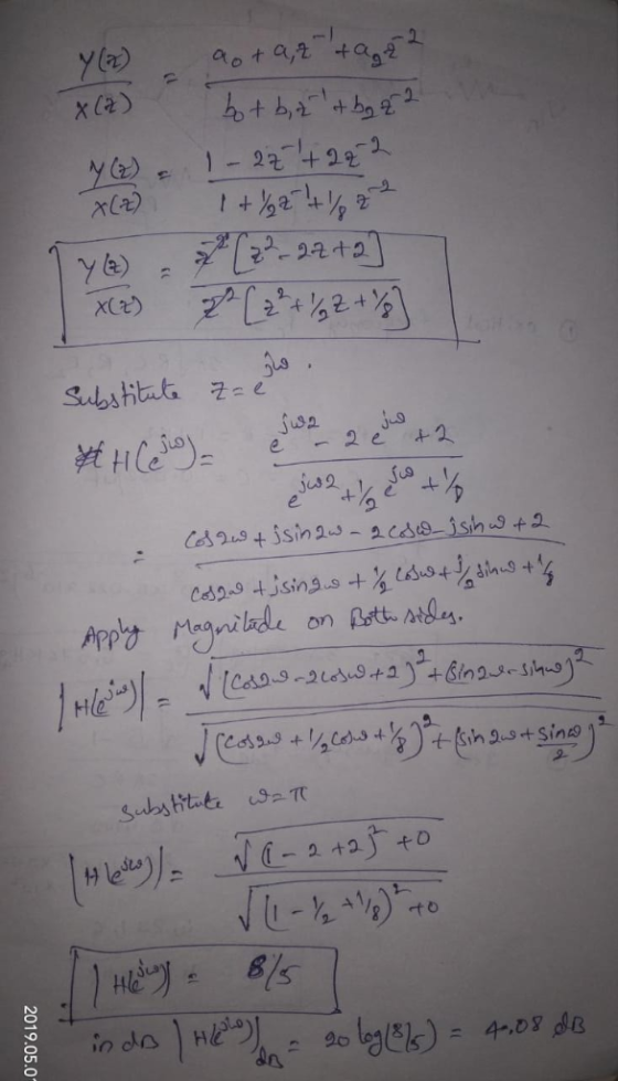
The filter coefficients of a second-order digital IIR filter
are: a0 = 1, a1 = -2, a2 = 2,
b0 = 1, b1 = 1/2, b2 = 1/8. (a's
are numerator coefficients and b's are the denominator
coefficients). Determine the magnitude response (in dB) at ω =
π.
Homework Answers

Add Answer to:
The filter coefficients of a second-order digital IIR filter
are: a0 = 1, a1 = -2,...
The filter coefficients of a second-order digital IIR filter are: a0 = 1, a1 = -2,...
The filter coefficients of a second-order digital IIR filter are: a0 = 1, a1 = -2, a2 = 2, b0 = 1, b1 = 1/2, b2 = 1/8. (a's are numerator coefficents and b's are the denominator coefficients). Determine the value of the impulse response h(6)?
1.The filter coefficients of a second-order digital IIR filter are: a0 = 1, a1 = -2,...
1.The filter coefficients of a second-order digital IIR filter are: a0 = 1, a1 = -2, a2 = 2, b0 = 1, b1 = 1/2, b2 = 1/8. (a's are numerator coefficents and b's are the denominator coefficients). Compute the magnitude response |H(ejω)| where ω = 5.174 rad/sec. 2. It is desired to extract a constant signal s(n)= s from the noisy measured signal x(n)= s(n)+v(n)= s + v(n), where v(n) is zero-mean white Gaussian noise of variance ϭv2. For...
QUESTION 28 3 points Save The Siter coefficients of a second-order digital IR filter are: ao-1,a1-2, a2-2, bo-1. b1-1/2, b2 1/8. (a's are numerator coetficients and b's are the denom...
 QUESTION 28 3 points Save The Siter coefficients of a second-order digital IR filter are: ao-1,a1-2, a2-2, bo-1. b1-1/2, b2 1/8. (a's are numerator coetficients and b's are the denominator coefficients). Determine the value of the impulse response N4? QUESTION 29 6 points Save Answer An image is to be sampled with a signal-to-quantisation ratio of at least 55 dB. The image samples are non-negative. The image sample values fall within the range from 0 to 1. How many bits...
Lİde-7981 1 1-1 &content-id~-1837836-1 &stepenu QUESTION 17 4 poin It is desired to extract a constant signal sío- s from the noisy measured signal kin- stowostvo.where vin) is zero-...
 Lİde-7981 1 1-1 &content-id~-1837836-1 &stepenu QUESTION 17 4 poin It is desired to extract a constant signal sío- s from the noisy measured signal kin- stowostvo.where vin) is zero- mean white Gaussian noise of variance ov. For that purpose. the following IIR lowpass fiter is used where a and b are arbitrary constants (0 < a < 1). Estimate the value of the cut-off frequency wcif a -0.8. QUESTION 18 3 poi The filter coefficients of a second-order digital IR...
QUESTION 6 Зро Design a second-order IIR digital low-pass filter using Butterworth approximation....
 QUESTION 6 Зро Design a second-order IIR digital low-pass filter using Butterworth approximation. Use the bilinear transformation to convert the analogue fiter to a digital one (choose the sampling period T- 2 s and the cut-off frequency as 1 rad/'s). Express the digital transfer function of the filter H(z) as: In the box below, provide the numerical answer for b1. [Note: Don't normalise the transfer func on, i.e. b0 # 1). r98111acontentid1837836_1&step QUESTION 7 Windowing based FIR filter design techniques...
A digital low pass IIR filter is to be designed with Butterworth approximation using the Bilinear transformation
A digital low pass IIR filter is to be designed with Butterworth approximation using the Bilinear transformation technique having the following specifications:(i) Passband magnitude is constant within 1 dB for frequencies below 0.2 π.(ii) Stopband attenuation is greater than 15 dB for frequencies between 0.3 π to π. Determine the order of the filter, cutoff frequency, poles location and transfer function of digital filter in order to meet the above specifications.
Using filterDesigner in MATLAB, design a second order low pass IIR Butterworth filter whose sampling frequency (Fs) is 1...
Using filterDesigner in MATLAB, design a second order low pass IIR Butterworth filter whose sampling frequency (Fs) is 1 kHz and cutoff frequency (Fc) is 10 Hz. Find the numerator and denominator coefficients. Write its transfer function H(z) = Y(z) / X(z). Write its difference function y(k). Draw (copy from Filter Designer) the magnitude response plot. Draw (copy from Filter Designer) the phase response plot. Draw (copy from Filter Designer) the impulse response plot.
Using filterDesigner in MATLAB, design a second order low pass IIR Butterworth filter whose sampling frequency...
Using filterDesigner in MATLAB, design a second order low pass IIR Butterworth filter whose sampling frequency (Fs) is 1 kHz and cutoff frequency (Fc) is 10 Hz. Find the numerator and denominator coefficients. Write its transfer function H(z) = Y(z) / X(z). Write its difference function y(k). Draw (copy from Filter Designer) the magnitude response plot. Draw (copy from Filter Designer) the phase response plot. Draw (copy from Filter Designer) the impulse response plot.
Determine the coefficients b0, b1, b2, of a generalized linear-phase FIR filter 1. (GLP FIR Filters]...
 Determine the coefficients b0,
b1, b2, of a generalized linear-phase FIR filter
1. (GLP FIR Filters] Determine the coefficients bo, bi, b2, of a generalized linear-phase FIR filter | d[n] = box[n] + b n - 1]+b22[n – 2] such that (i) it rejects any frequency component at wo = /3; and (ii) its frequency response is normalized so that Ha(0) = 1. Compute and sketch the magnitude and phase response of the filter to check that it satisfies the...
Determine the coefficients b0,
b1, b2, of a generalized linear-phase FIR filter
1. (GLP FIR Filters] Determine the coefficients bo, bi, b2, of a generalized linear-phase FIR filter | d[n] = box[n] + b n - 1]+b22[n – 2] such that (i) it rejects any frequency component at wo = /3; and (ii) its frequency response is normalized so that Ha(0) = 1. Compute and sketch the magnitude and phase response of the filter to check that it satisfies the...
1. By using an analog filter with a Butterworth response of order 3, design a digital IIR low pass filter with 3-db cutoff frequency 2c 0.6TT a) b) c) Evaluate the transfer function of the analog fil...
 1. By using an analog filter with a Butterworth response of order 3, design a digital IIR low pass filter with 3-db cutoff frequency 2c 0.6TT a) b) c) Evaluate the transfer function of the analog filter (10marks) Skecth the block diagram of transfer function (5 marks) Plot the magnitude response of the filters. (5marks)
1. By using an analog filter with a Butterworth response of order 3, design a digital IIR low pass filter with 3-db cutoff frequency 2c...
1. By using an analog filter with a Butterworth response of order 3, design a digital IIR low pass filter with 3-db cutoff frequency 2c 0.6TT a) b) c) Evaluate the transfer function of the analog filter (10marks) Skecth the block diagram of transfer function (5 marks) Plot the magnitude response of the filters. (5marks)
1. By using an analog filter with a Butterworth response of order 3, design a digital IIR low pass filter with 3-db cutoff frequency 2c...
 QUESTION 28 3 points Save The Siter coefficients of a second-order digital IR filter are: ao-1,a1-2, a2-2, bo-1. b1-1/2, b2 1/8. (a's are numerator coetficients and b's are the denominator coefficients). Determine the value of the impulse response N4? QUESTION 29 6 points Save Answer An image is to be sampled with a signal-to-quantisation ratio of at least 55 dB. The image samples are non-negative. The image sample values fall within the range from 0 to 1. How many bits...
 Lİde-7981 1 1-1 &content-id~-1837836-1 &stepenu QUESTION 17 4 poin It is desired to extract a constant signal sío- s from the noisy measured signal kin- stowostvo.where vin) is zero- mean white Gaussian noise of variance ov. For that purpose. the following IIR lowpass fiter is used where a and b are arbitrary constants (0 < a < 1). Estimate the value of the cut-off frequency wcif a -0.8. QUESTION 18 3 poi The filter coefficients of a second-order digital IR...
 QUESTION 6 Зро Design a second-order IIR digital low-pass filter using Butterworth approximation. Use the bilinear transformation to convert the analogue fiter to a digital one (choose the sampling period T- 2 s and the cut-off frequency as 1 rad/'s). Express the digital transfer function of the filter H(z) as: In the box below, provide the numerical answer for b1. [Note: Don't normalise the transfer func on, i.e. b0 # 1). r98111acontentid1837836_1&step QUESTION 7 Windowing based FIR filter design techniques...
 Determine the coefficients b0,
b1, b2, of a generalized linear-phase FIR filter
1. (GLP FIR Filters] Determine the coefficients bo, bi, b2, of a generalized linear-phase FIR filter | d[n] = box[n] + b n - 1]+b22[n – 2] such that (i) it rejects any frequency component at wo = /3; and (ii) its frequency response is normalized so that Ha(0) = 1. Compute and sketch the magnitude and phase response of the filter to check that it satisfies the...
Determine the coefficients b0,
b1, b2, of a generalized linear-phase FIR filter
1. (GLP FIR Filters] Determine the coefficients bo, bi, b2, of a generalized linear-phase FIR filter | d[n] = box[n] + b n - 1]+b22[n – 2] such that (i) it rejects any frequency component at wo = /3; and (ii) its frequency response is normalized so that Ha(0) = 1. Compute and sketch the magnitude and phase response of the filter to check that it satisfies the...
 1. By using an analog filter with a Butterworth response of order 3, design a digital IIR low pass filter with 3-db cutoff frequency 2c 0.6TT a) b) c) Evaluate the transfer function of the analog filter (10marks) Skecth the block diagram of transfer function (5 marks) Plot the magnitude response of the filters. (5marks)
1. By using an analog filter with a Butterworth response of order 3, design a digital IIR low pass filter with 3-db cutoff frequency 2c...
1. By using an analog filter with a Butterworth response of order 3, design a digital IIR low pass filter with 3-db cutoff frequency 2c 0.6TT a) b) c) Evaluate the transfer function of the analog filter (10marks) Skecth the block diagram of transfer function (5 marks) Plot the magnitude response of the filters. (5marks)
1. By using an analog filter with a Butterworth response of order 3, design a digital IIR low pass filter with 3-db cutoff frequency 2c...
Most questions answered within 3 hours.
-
The commercial lending department of First Bank made a
substantial loan to Alpha Company after obtaining...
asked 24 seconds ago -
For a reaction, reagents --->products, it's forwarding rate
(rate of products formation) is proportional to the...
asked 13 minutes ago -
5)
Typically,
there will need to be a rather high degree of coordination and
interaction among...
asked 9 minutes ago -
if the marginal revenue on each MRI is $2500, and the
marginal cost for each is...
asked 11 minutes ago -
The amounts of nicotine in a certain brand of cigarette are
normally distributed with a mean...
asked 14 minutes ago -
What did Butler and Hobbes contribute to our understanding of
utilitarianism?
asked 16 minutes ago -
History
Lincoln's religious thought was almost exclusively shaped by his
Calvinist upbringing.
True
False
QUESTION 6...
asked 15 minutes ago -
In a two-way factorial ANOVA, the final F-ratio for
factor AxB is determined by dividing _____...
asked 16 minutes ago -
If 1.6g of CH4 reacts with oxygen gas to form water and carbon
dioxide what is...
asked 14 minutes ago -
Applying the content from Primal Leadership, and the format
Personal Change Plan on p. 110 Boyatzis...
asked 17 minutes ago -
Your black labrador has a genotype of BbEe.
Which of the following is correct? Select all...
asked 21 minutes ago -
Which of the following statements explains why the cost of
advertising might be relevant to a...
asked 31 minutes ago