

Homework Answers


Add Answer to:
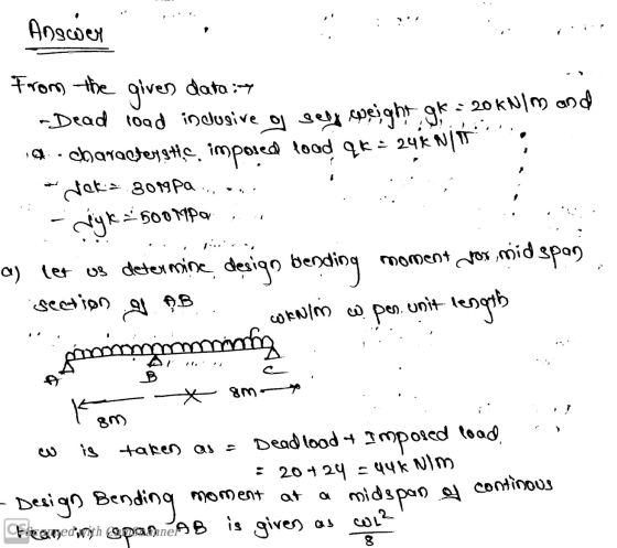
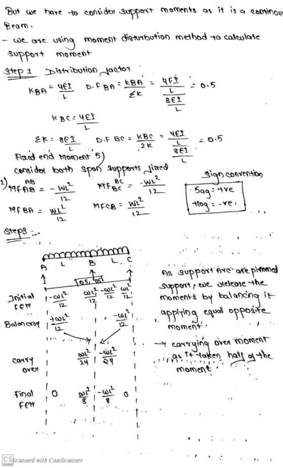
Fig. Q-1 shows a two-span continuous beam which is to carry a characteristic dead load inclusive...
all parts A simply supported concrete beam is to be designed to span 8m. The beam...
 all parts
A simply supported concrete beam is to be designed to span 8m. The beam is required to resist a dead load of 40 kN/m (which includes an allowance for self-weight) and an imposed load of 20 kN/m Calculate the ultimate design load that the beam will be required to resist and hence calculate the ultimate design moment. (10 Marks] b) Choose an appropriate depth and width of the beam. [5 marks] c) Calculate an appropriate amount of reinforcing...
all parts
A simply supported concrete beam is to be designed to span 8m. The beam is required to resist a dead load of 40 kN/m (which includes an allowance for self-weight) and an imposed load of 20 kN/m Calculate the ultimate design load that the beam will be required to resist and hence calculate the ultimate design moment. (10 Marks] b) Choose an appropriate depth and width of the beam. [5 marks] c) Calculate an appropriate amount of reinforcing...
A simply supported reinforced concrete beam of 8 m span is subjected to uniformly distributed load...
 A simply supported reinforced concrete beam of 8 m span is subjected to uniformly distributed load as shown in Figure 3. The following data are given: The ultimate load, wu is 60 kN/m; characteristic strength of concrete, fck is 30 N/mm²; characteristic strength of reinforcement, fyk is 500 N/mm2. The effective depth, d is 650 mm. Take the link diameter, w as 10 mm, main bar diameter, o as 20 mm and concrete cover as 30 mm. Design the shear...
A reinforced concrete cantilevered beam with a span of 5 m extends from the wall, as shown in the...
 A reinforced concrete cantilevered beam with a span of 5 m extends from the wall, as shown in the figure below. The beam has a rectangular cross-section and supports a uniform dead load (DL) of 15 kN/m (excluding the self-weight) and a uniform live load (LL) of 25 kN/m. The beam width is restricted to 400 mm. Use 10M stirrups and 25M bars for tension steel. The maximum aggregate size is 20 mm. 1ie 5.5. beam is located in the...
2. A rectangular beam, 400 x 600 mm gross dimension, is cast using a concrete strength...
 2. A rectangular beam, 400 x 600 mm gross dimension, is cast using a concrete strength of fc 30 MPa, reinforced with 5-25 mm diameter steel bar at the effective depth of 500 mm. If is subjected to a moment, M 130 kN-m. Determine the following: Magnitude of the bending moment that cracks the singly-reinforced beam section. (10 pts) b. For the computed cracking moment, determine the maximum compressive stress in the concrete and the stress in the tension steel....
Q4 A Cantilever rectangular beam of 2m span carries characteristic pearmeant action (Excluding self weight of...
 Q4 A Cantilever rectangular beam of 2m span carries characteristic pearmeant action (Excluding self weight of beam) of 6.5 KN/m and variable action of 5.5KN/m along with point load 4.5 KN at free end respectively. The beam dimensions are breadth-300mm effective depth-360mm. Assuming the following material strengths, calculate the area of reinforcement required. Fck-30N/mm2, Fyk-500N/mm2.d'-25mm [Ans-Ası -815 mm2 2T25 ф-982mmal 00 0000 00 00 00O
if you can just do a and b ( would be appreciate ) i need to learn the concept Fig. Q.1 2. A steel plate (Fig. Q.2) is riveted to a vertical pillar diameter and carry the load and moment resul...
 if you can just do a and b ( would be appreciate ) i
need to learn the concept
Fig. Q.1 2. A steel plate (Fig. Q.2) is riveted to a vertical pillar diameter and carry the load and moment resulting fro he rivets have a 15 mm civeted to from the external load of 8 KN. eters. The yield strengths of the materials are I length dimensions are in The (Sy)mvet 600 MPa and (Sy)plate 350 MPa. Calculate the...
if you can just do a and b ( would be appreciate ) i
need to learn the concept
Fig. Q.1 2. A steel plate (Fig. Q.2) is riveted to a vertical pillar diameter and carry the load and moment resulting fro he rivets have a 15 mm civeted to from the external load of 8 KN. eters. The yield strengths of the materials are I length dimensions are in The (Sy)mvet 600 MPa and (Sy)plate 350 MPa. Calculate the...
5. Determine the mid-span short-term deflection of a simply supported beam with the section shown in...
 5. Determine the mid-span short-term deflection of a simply supported beam with the section shown in Figure Q5. Design data: Concrete strength: fcu 30 MPa. Area of tensile steel reinforcement: As 1500 mm Area of compressive steel reinforcement: A,-1500 mm2 Instantaneous static modulus of elasticity of concrete = 25GPa. Span -8.0 m Loading: Dead load 5.0 kN/m (uniformly distributed load); Live load 5.0 kN/m (uniformly distributed load) (Hint: the height of neutral axis of the mid-span section under the service...
(a) Figure Q3 (a) shows a cantilever beam which is carry a load P at point...
 (a) Figure Q3 (a) shows a cantilever beam which is carry a load P at point C. (1) Sketch the deflection curve of the beam. (2 marks) t (ii) Derive the bending moment deflection, slope deflection and deflection equation at b-b using Double Integration Method. (10 marks) FIGURE Q3 (a) Calculate the maximum deflection. Given: = 10 m a = 3 m P = 25 KN El is constant d 100 mm D (5 marks) 200 mm t6 mm (b)...
2. A steel plate (Fig Q.2) is riveted to a vertical pillar. The three rivets have a 15mm diameter and carry the load and moment resulting from the external load of 8 N All length dmensions are...
 2. A steel plate (Fig Q.2) is riveted to a vertical pillar. The three rivets have a 15mm diameter and carry the load and moment resulting from the external load of 8 N All length dmensions are in milimeters. The yield strengths of the matenials are (S 600 MPa and (S 350 MPa. Calculate the safety factors for a Shear of rivet when Say 0.57 S (10 pts) b. Bearing of met when σ--o 9 s, (10 pts) c Beanng...
The continuous beam shown in Fig. 1 is part of a beam-and-slab floor system of an...
 The continuous beam shown in Fig. 1 is part of a beam-and-slab floor system of an office building and is typical of a series of beams spaced at 4 m intervals. In addition to the dead load, the live load on the floor is 3 kPa. Using f'c = 32MPa, N32 bars for main reinforcement, a) Find the maximum positive and negative moments using the AS3600 simplified method. b) Design the beam cross-section for the maximum amount of tensile steel...
 all parts
A simply supported concrete beam is to be designed to span 8m. The beam is required to resist a dead load of 40 kN/m (which includes an allowance for self-weight) and an imposed load of 20 kN/m Calculate the ultimate design load that the beam will be required to resist and hence calculate the ultimate design moment. (10 Marks] b) Choose an appropriate depth and width of the beam. [5 marks] c) Calculate an appropriate amount of reinforcing...
all parts
A simply supported concrete beam is to be designed to span 8m. The beam is required to resist a dead load of 40 kN/m (which includes an allowance for self-weight) and an imposed load of 20 kN/m Calculate the ultimate design load that the beam will be required to resist and hence calculate the ultimate design moment. (10 Marks] b) Choose an appropriate depth and width of the beam. [5 marks] c) Calculate an appropriate amount of reinforcing...
 A simply supported reinforced concrete beam of 8 m span is subjected to uniformly distributed load as shown in Figure 3. The following data are given: The ultimate load, wu is 60 kN/m; characteristic strength of concrete, fck is 30 N/mm²; characteristic strength of reinforcement, fyk is 500 N/mm2. The effective depth, d is 650 mm. Take the link diameter, w as 10 mm, main bar diameter, o as 20 mm and concrete cover as 30 mm. Design the shear...
 A reinforced concrete cantilevered beam with a span of 5 m extends from the wall, as shown in the figure below. The beam has a rectangular cross-section and supports a uniform dead load (DL) of 15 kN/m (excluding the self-weight) and a uniform live load (LL) of 25 kN/m. The beam width is restricted to 400 mm. Use 10M stirrups and 25M bars for tension steel. The maximum aggregate size is 20 mm. 1ie 5.5. beam is located in the...
 2. A rectangular beam, 400 x 600 mm gross dimension, is cast using a concrete strength of fc 30 MPa, reinforced with 5-25 mm diameter steel bar at the effective depth of 500 mm. If is subjected to a moment, M 130 kN-m. Determine the following: Magnitude of the bending moment that cracks the singly-reinforced beam section. (10 pts) b. For the computed cracking moment, determine the maximum compressive stress in the concrete and the stress in the tension steel....
 Q4 A Cantilever rectangular beam of 2m span carries characteristic pearmeant action (Excluding self weight of beam) of 6.5 KN/m and variable action of 5.5KN/m along with point load 4.5 KN at free end respectively. The beam dimensions are breadth-300mm effective depth-360mm. Assuming the following material strengths, calculate the area of reinforcement required. Fck-30N/mm2, Fyk-500N/mm2.d'-25mm [Ans-Ası -815 mm2 2T25 ф-982mmal 00 0000 00 00 00O
 if you can just do a and b ( would be appreciate ) i
need to learn the concept
Fig. Q.1 2. A steel plate (Fig. Q.2) is riveted to a vertical pillar diameter and carry the load and moment resulting fro he rivets have a 15 mm civeted to from the external load of 8 KN. eters. The yield strengths of the materials are I length dimensions are in The (Sy)mvet 600 MPa and (Sy)plate 350 MPa. Calculate the...
if you can just do a and b ( would be appreciate ) i
need to learn the concept
Fig. Q.1 2. A steel plate (Fig. Q.2) is riveted to a vertical pillar diameter and carry the load and moment resulting fro he rivets have a 15 mm civeted to from the external load of 8 KN. eters. The yield strengths of the materials are I length dimensions are in The (Sy)mvet 600 MPa and (Sy)plate 350 MPa. Calculate the...
 5. Determine the mid-span short-term deflection of a simply supported beam with the section shown in Figure Q5. Design data: Concrete strength: fcu 30 MPa. Area of tensile steel reinforcement: As 1500 mm Area of compressive steel reinforcement: A,-1500 mm2 Instantaneous static modulus of elasticity of concrete = 25GPa. Span -8.0 m Loading: Dead load 5.0 kN/m (uniformly distributed load); Live load 5.0 kN/m (uniformly distributed load) (Hint: the height of neutral axis of the mid-span section under the service...
 (a) Figure Q3 (a) shows a cantilever beam which is carry a load P at point C. (1) Sketch the deflection curve of the beam. (2 marks) t (ii) Derive the bending moment deflection, slope deflection and deflection equation at b-b using Double Integration Method. (10 marks) FIGURE Q3 (a) Calculate the maximum deflection. Given: = 10 m a = 3 m P = 25 KN El is constant d 100 mm D (5 marks) 200 mm t6 mm (b)...
 2. A steel plate (Fig Q.2) is riveted to a vertical pillar. The three rivets have a 15mm diameter and carry the load and moment resulting from the external load of 8 N All length dmensions are in milimeters. The yield strengths of the matenials are (S 600 MPa and (S 350 MPa. Calculate the safety factors for a Shear of rivet when Say 0.57 S (10 pts) b. Bearing of met when σ--o 9 s, (10 pts) c Beanng...
 The continuous beam shown in Fig. 1 is part of a beam-and-slab floor system of an office building and is typical of a series of beams spaced at 4 m intervals. In addition to the dead load, the live load on the floor is 3 kPa. Using f'c = 32MPa, N32 bars for main reinforcement, a) Find the maximum positive and negative moments using the AS3600 simplified method. b) Design the beam cross-section for the maximum amount of tensile steel...
Most questions answered within 3 hours.
-
(Covered Interest Arbitrage) Harry Norman, a foreign exchange
trader at UBS’s office in Tokyo has $2,000,000...
asked 2 minutes ago -
The structure of an advertising campaign is:
a.the process of preparing and integrating a
specific...
asked 1 minute ago -
Suppose the lengths of human pregnancies are normally
distributed with
muμequals=266
days and
sigmaσequals=16
days. Complete...
asked 9 minutes ago -
a sample of the labor costs per hour to assemble a product has a
mean of...
asked 19 minutes ago -
Choose all that are true:
A)
A FileReader object can be passed to BufferedReader or Scanner...
asked 16 minutes ago -
Research taking place at Stanford University has been a
consistent force in the development of Silicon...
asked 21 minutes ago -
what evidence is there that mitochondria and chloroplasts
originated from ancient prokaryotes and why?
asked 25 minutes ago -
A Mg|Mg2+ ||
Ni2+|Ni galvanic cell
is constructed in which the standard cell voltage is
2.12...
asked 25 minutes ago -
An organization's routine purchase changes when a supplier
discontinues a product. In such a situation, which...
asked 37 minutes ago -
Like Jupiter's moon Europa, Saturn's moon Enceladus is high on
our list for exploration. List and...
asked 40 minutes ago -
Problem 9-21
(Algorithmic) (LO. 2, 3)
Taylor, age 16, is a
dependent of her parents. For...
asked 50 minutes ago -
An egg is thrown nearly vertically upward from a point near the
cornice of a tall...
asked 46 minutes ago