
Homework Answers

Add Answer to:
For
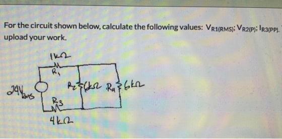
the circuit shown below, calculate the following values: VR1(rms),
VR2(p); IR3(pp)
For the circuit shown...
Chapter 9, Problem 9.051 (Circuit Solution) х] Incorrect. Calculate the rms value of the waveform shown...
 Chapter 9, Problem 9.051 (Circuit Solution) х] Incorrect. Calculate the rms value of the waveform shown in the figure below. (0) (0) АЛ 06 12 18 24 30 36 t(s) X 0.866 V the tolerance is +/-2%
Question 31 (17 points) 120/120 single-phase transformer. Calculate the values for the equivalent circuit for the single-phase transformer for the given short and open circuit test shown below. (2 po...
 Question 31 (17 points) 120/120 single-phase transformer. Calculate the values for the equivalent circuit for the single-phase transformer for the given short and open circuit test shown below. (2 points) Draw the equivalent circuit. (1 point each) Find Ssc, QSC, Soc, Qoc, R1, R2, XI, X2, Rc, Xm, PFsc, PFoc, (esc θ。c) phase angel between V and I. What is the power rating of this transformer? Short circuit test (performed at High Voltage side) Vsc 16.20V rms, Isc 5.00 A...
Voltage and Current Division For the circuit shown, calculate V. V and Vs when V. =...
 Voltage and Current Division For the circuit shown, calculate V. V and Vs when V. = 7 V, R; = 18 2. R2 = 66 2. R3 = 57 2. R4 = 37 and Rs = 332 Express your answer to two significant figures, with appropriate units View Available Hint(s) @? R-180 R2 = 660 + V + 12 0.597 V = 7 V R3 - 570 V 1.89 V R$ = 33 R = 37 Vs + - V4...
14) In the combination circuit shown below, you are given several resistors that are connected in...
 14) In the combination circuit shown below, you are given several resistors that are connected in various ways. a) Find the equivalent resistances of the circuit given the following values for the resistors (using series and parallel): b) Calculate the potential difference for this reduced circuit SHOW ALL WORK... OR NO CREDIT R: 499 519 Mr. 809 R, 372 759 Fri W R. R 45 I
For the circuit shown in the figure below, calculate the following quantities. (Assume E = 9.00...
 For the circuit shown in the figure below, calculate the following quantities. (Assume E = 9.00 V and R = 7.50 ) 12.0 V 4.00 2 Hemo 2.00 w + R E (a) the current in the 2.00-n resistor (Enter the magnitude.) mA (b) the potential difference between points a and b V Additional Materials eBook
Please answer the following question and show all work: Problem 1: For the circuit shown below,...
 Please answer the following question and show all work:
Problem 1: For the circuit shown below, use Kirchhoff's laws to calculate the currents 1, 12, 13. 40 1 40 20 V 2V 10V w OE OZ 3 40
Please answer the following question and show all work:
Problem 1: For the circuit shown below, use Kirchhoff's laws to calculate the currents 1, 12, 13. 40 1 40 20 V 2V 10V w OE OZ 3 40
Styles The circuit shown below uses the following values: E= 12 V R1 = 5.6 KO...
 Styles The circuit shown below uses the following values: E= 12 V R1 = 5.6 KO R2 = 47 KO R3 = 4.7 KO R = 2.2 KO R = 3.3 KO R3 + Un V V unr E R2 RA } V 12 RA mi 4. Calculate : Vi = V2 = V3 = VL = 11 = 12 = 13 = Calculate Vrh Calculate RTH
(25 credits) For circuit shown in the figure below do the following: Rs Ro Rs с,...
 (25 credits) For circuit shown in the figure below do the following: Rs Ro Rs с, R, Rj Ri 100 k Rs= R,-10 k C3-100 nF R2 = 10k R,-10M C-10 nF Simplify your expressions as much as possible. First solve using variables and substitute values at the end (a) (2 credits) What type of configuration Operational Amplifier 1 shows? You answer: (b) (2 credits) What type of configuration Operational Amplifier 2 shows? You answer (c) (I credit) Use impedances...
Impedance, Power, Phasor of RC Circuit a. Given a circuit below, calculate and draw the following...
 Impedance, Power, Phasor of RC Circuit a. Given a circuit below, calculate and draw the following quantities: Z, Ez, Iz, P, Q, S and draw their Phasors Iz 11 Es 100 V E1 Ez R 171 22 Xc 2002 b. Given a wiring circuit and measuring instruments, draw its corresponding circuit / schematic (similar to circuit of question 5.a. above) Ooo POWER MUS V BA BURY RESISTIVE LOAD DATA ACQUISITION INTERFACE 2 ON VIA ARAYANI ºooo ON N ON BAT...
126 S. Consider the large circuit shown in Figure 3, where the components have the following values: We will use...
 126 S. Consider the large circuit shown in Figure 3, where the components have the following values: We will use Kirchhoff's rules to calculate the current passing through each of the nineteen circuit components. ineteen components in this circuit, there are only twelve through two components that are in series. After considering this fact, draw twelve arrows on Figure 3, indicating twelve distinct currents. Label these currents as 112 These twelve currents are unknown, and we wish to find their...
 Chapter 9, Problem 9.051 (Circuit Solution) х] Incorrect. Calculate the rms value of the waveform shown in the figure below. (0) (0) АЛ 06 12 18 24 30 36 t(s) X 0.866 V the tolerance is +/-2%
 Question 31 (17 points) 120/120 single-phase transformer. Calculate the values for the equivalent circuit for the single-phase transformer for the given short and open circuit test shown below. (2 points) Draw the equivalent circuit. (1 point each) Find Ssc, QSC, Soc, Qoc, R1, R2, XI, X2, Rc, Xm, PFsc, PFoc, (esc θ。c) phase angel between V and I. What is the power rating of this transformer? Short circuit test (performed at High Voltage side) Vsc 16.20V rms, Isc 5.00 A...
 Voltage and Current Division For the circuit shown, calculate V. V and Vs when V. = 7 V, R; = 18 2. R2 = 66 2. R3 = 57 2. R4 = 37 and Rs = 332 Express your answer to two significant figures, with appropriate units View Available Hint(s) @? R-180 R2 = 660 + V + 12 0.597 V = 7 V R3 - 570 V 1.89 V R$ = 33 R = 37 Vs + - V4...
 14) In the combination circuit shown below, you are given several resistors that are connected in various ways. a) Find the equivalent resistances of the circuit given the following values for the resistors (using series and parallel): b) Calculate the potential difference for this reduced circuit SHOW ALL WORK... OR NO CREDIT R: 499 519 Mr. 809 R, 372 759 Fri W R. R 45 I
 For the circuit shown in the figure below, calculate the following quantities. (Assume E = 9.00 V and R = 7.50 ) 12.0 V 4.00 2 Hemo 2.00 w + R E (a) the current in the 2.00-n resistor (Enter the magnitude.) mA (b) the potential difference between points a and b V Additional Materials eBook
 Please answer the following question and show all work:
Problem 1: For the circuit shown below, use Kirchhoff's laws to calculate the currents 1, 12, 13. 40 1 40 20 V 2V 10V w OE OZ 3 40
Please answer the following question and show all work:
Problem 1: For the circuit shown below, use Kirchhoff's laws to calculate the currents 1, 12, 13. 40 1 40 20 V 2V 10V w OE OZ 3 40
 Styles The circuit shown below uses the following values: E= 12 V R1 = 5.6 KO R2 = 47 KO R3 = 4.7 KO R = 2.2 KO R = 3.3 KO R3 + Un V V unr E R2 RA } V 12 RA mi 4. Calculate : Vi = V2 = V3 = VL = 11 = 12 = 13 = Calculate Vrh Calculate RTH
 (25 credits) For circuit shown in the figure below do the following: Rs Ro Rs с, R, Rj Ri 100 k Rs= R,-10 k C3-100 nF R2 = 10k R,-10M C-10 nF Simplify your expressions as much as possible. First solve using variables and substitute values at the end (a) (2 credits) What type of configuration Operational Amplifier 1 shows? You answer: (b) (2 credits) What type of configuration Operational Amplifier 2 shows? You answer (c) (I credit) Use impedances...
 Impedance, Power, Phasor of RC Circuit a. Given a circuit below, calculate and draw the following quantities: Z, Ez, Iz, P, Q, S and draw their Phasors Iz 11 Es 100 V E1 Ez R 171 22 Xc 2002 b. Given a wiring circuit and measuring instruments, draw its corresponding circuit / schematic (similar to circuit of question 5.a. above) Ooo POWER MUS V BA BURY RESISTIVE LOAD DATA ACQUISITION INTERFACE 2 ON VIA ARAYANI ºooo ON N ON BAT...
 126 S. Consider the large circuit shown in Figure 3, where the components have the following values: We will use Kirchhoff's rules to calculate the current passing through each of the nineteen circuit components. ineteen components in this circuit, there are only twelve through two components that are in series. After considering this fact, draw twelve arrows on Figure 3, indicating twelve distinct currents. Label these currents as 112 These twelve currents are unknown, and we wish to find their...
Most questions answered within 3 hours.
-
The free energy change for the following reaction at 25 °C, when
[Sn2+] = 1.17 M...
asked 1 hour ago -
An MNE is this kind of industry when competition in one country
is essentially independent of...
asked 2 hours ago -
. For this set of questions, determine what
proportion of a normal distribution is located betweeneach...
asked 3 hours ago -
A college student is employed as a door-to-door newspaper
salesman. Historical data suggests that the student...
asked 4 hours ago -
MATLAB HW 11 problem using Switch Case and Input commands
Write a script file that calculates...
asked 4 hours ago -
Considering gravitational time dilation, calculate the time that
passes in Earth’s surface while 1 hour passes...
asked 4 hours ago -
Minitab Problem: Take the Lake Hume June rainfall data and find
use the processes outlined in...
asked 5 hours ago -
X Company is trying to decide whether to continue using old
equipment to make Product A...
asked 5 hours ago -
IN PYTHON ONLY !! Program 2: Re-work
program #5 (WeeklyHours) from the previous assignment such that...
asked 6 hours ago -
The average length of time between arrivals at a turnpike
toll-booth is 26 seconds. What is...
asked 7 hours ago -
(a) A piston at 6.1 atm contains a gas that occupies a volume of
3.5 L....
asked 9 hours ago -
Please answer true or false. Words
cannot be changed or added in to make it true...
asked 9 hours ago