
Homework Answers

![E [K]- Laves 42 AS e E for element 3 0.75116 -C-43351-0-75116 0:43335 +0.43335 0.25 10.43335 : -0.25 192 F075116 0:43335 0.75](http://img.homeworklib.com/questions/f7a13e90-7cb0-11ec-a751-bbcc475cd5e7.png?x-oss-process=image/resize,w_560)

![Since. F- [K]: [c] Exi 53 Sincle 42 F५० Exy - Vivi, Uz Vz, UVA zo. - U₂ V2 = ? Fy= Pcos B = 250 N T J Fag = Psin B = 433 N S](http://img.homeworklib.com/questions/f8f9a5a0-7cb0-11ec-a9d7-9d9d345aa743.png?x-oss-process=image/resize,w_560)
![☆ Shers; Cola Ernem de m] 10.7 0.8007.- 0.8067 0 SSN V21 [-] = 2.854 xíc? Nm 2. - Set Cover 05 c2c 0877 Ea- Episu say | set •](http://img.homeworklib.com/questions/f98adbb0-7cb0-11ec-8ae9-d1dc2f213f15.png?x-oss-process=image/resize,w_560)
![1 .&, Strain : fim ] ro Vz : -0.8007 -0.5 0.8167 05 355 V2 , DIXG4 = 3 tur 4-r]73 - Ez = 42X166 > C3 6:45-a donna > Scanned](http://img.homeworklib.com/questions/fa1e15a0-7cb0-11ec-8600-bfb10319c289.png?x-oss-process=image/resize,w_560)
Add Answer to:
4. Consider the 2D truss system shown below which contains only pinned connections. The length of...
The truss shown below is supported by a pinned support at A and roller support at...
 The truss shown below is supported by a pinned support at A and roller support at C. The length of the members is shown in the Figure below. Set the forces acting on the truss as P1 = 9 kN, P2 = 15 kN. PF 3 m - 5. State whether the members CE and CB are in tension or compression. 6. Determine the cross-sectional areas of the members CE and CB. The stresses are not to exceed 20.2 MPa...
Please solve this question clearly and step by step. Thank you 2. A truss assembly shown...
 Please solve this question clearly and step by step.
Thank you
2. A truss assembly shown in Figure Q2 below is made of aluminum alloy that has a modulus of elasticity, E = 69 GPa. member is 225 mm2 The cross sectional area of each 4300 N (0, 40) m (40, 40) m 2 500 N 3 (0, 0) FIGURE Q2 Determine the global stiffness matrix for the truss assembly. a. [10 marks] Determine the displacement at node 3. b....
Please solve this question clearly and step by step.
Thank you
2. A truss assembly shown in Figure Q2 below is made of aluminum alloy that has a modulus of elasticity, E = 69 GPa. member is 225 mm2 The cross sectional area of each 4300 N (0, 40) m (40, 40) m 2 500 N 3 (0, 0) FIGURE Q2 Determine the global stiffness matrix for the truss assembly. a. [10 marks] Determine the displacement at node 3. b....
The plane truss is subjected to a load as shown in Figure 4. Take E = 200 GPa and cross sectional areas of members 1, 2...
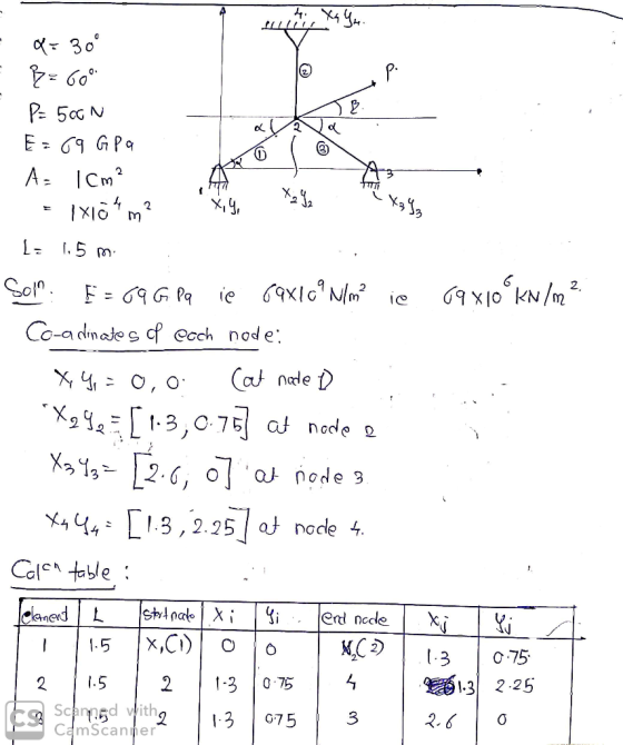
 The plane truss is subjected to a load as shown in Figure 4. Take E = 200 GPa and cross sectional areas of members 1, 2 and 3 as 150, 250 and 200 mm2 respectively a) Assemble the upper triangular part of the global stiffness matrix for the truss b) Determine the horizontal and vertical displacements at node 4 c) Calculate the forces in each member of the truss. (25 marks) 20 kN 3 60° 4 1.5m 2 2 20m...
QUESTION 10 The truss shown below is pinned at one end and has a roller at...
 QUESTION 10 The truss shown below is pinned at one end and has a roller at the other end. The truss is subjected to the forces, P and 2P, where P=12 kN. Compute the vertical displacement at B. Take E=205 GPa and A =50.0cm2. Give your answer to 2 decimal places in mm. Assume that the node will displace down. 2P kN PKN PkN 3 m 3 m G F E 1.5 m B 1.5 m D BE: -1.5 m...
A plane structure consists of three truss elements connected to four nodes, as shown below. All t...
 A plane structure consists of three truss elements connected to four nodes, as shown below. All trusses have cross sectional area A -7.104 m2 and elastic modulus E = 210 GPa. The length of each truss element is L = 1 m. A point force, P -5 kN, is acting on node 4 L/2 3.1 Calculate the displacements at the nodes 3.2 Calculate the reaction forces 3.3 Calculate the stress in each bar
A plane structure consists of three truss...
A plane structure consists of three truss elements connected to four nodes, as shown below. All trusses have cross sectional area A -7.104 m2 and elastic modulus E = 210 GPa. The length of each truss element is L = 1 m. A point force, P -5 kN, is acting on node 4 L/2 3.1 Calculate the displacements at the nodes 3.2 Calculate the reaction forces 3.3 Calculate the stress in each bar
A plane structure consists of three truss...
Question 4 The plane truss is subjected to a load as shown in Figure 4. Take E = 200 GPa and cross sectional areas of m...
 Question 4 The plane truss is subjected to a load as shown in Figure 4. Take E = 200 GPa and cross sectional areas of members 1, 2 and 3 as 150, 250 and 200 mm2 respectively a) Assemble the upper triangular part of the global stiffness matrix for the truss. b) Determine the horizontal and vertical displacements at node 4. c) Calculate the forces in each member of the truss. (25 marks) 20 kN 3 600 4 3 1.5m...
2. For the pin-jointed truss shown in Figure Q2.1 applied at node 4. The Young's modulus E(GPa) is the same for...
 2. For the pin-jointed truss shown in Figure Q2.1 applied at node 4. The Young's modulus E(GPa) is the same for the three truss vertical downward force P(kN) is a members. The cross sectional area of each of the truss members is indicated below and expressed in terms of a constant A. By using the stiffness method: (a) Compute the reduced stiffness matrix Kg [5 marks [10 marks (b) Calculate the global displacements of node 4 in terms of P,...
The cross-sectional area of each member of the truss shown in the figure is 4 =...
 The cross-sectional area of each member of the truss shown in the figure is 4 = 400 mm and E = 200 GPa. (a) Determine the vertical displacement of joint Cif a 4-KN force is applied to the truss at C. (b) If no loads act on the truss, what would be the vertical displacement of joint C if member AB were 5 mm too short? (c) If 4 kN force and fabrication error are both accounted, what would be...
Figure 2.11 Two-bar truss. -14 3 0 3-1 [A]=1 4 2.21 The potential energy of the...
 Figure 2.11 Two-bar truss. -14 3 0 3-1 [A]=1 4 2.21 The potential energy of the two-bar truss shown in Fig. 2.11 is given by s (2s where E is Young's modulus, A the cross-sectional area of each member, I the span or the tru s the length of each member, h the height of the truss the applied load, θ the angle at which the load is applied, and x and x are, respectively, the horizontal and vertical displacements...
blem 5 (25 points): Consider the system of bars shown below. Bars AB, CD, and EF...
 blem 5 (25 points): Consider the system of bars shown below. Bars AB, CD, and EF are connected d link BED. Determine the horizontal displacement of point F B by a rigid . Bar AB has a cross-sectional area of 0.012 m2, a Young's modulus of 200 GPa, and a length of 0.34 m. . Bar CD has a cross-sectional area of 0.010 m2, a Young's modulus of 200 GPa, and a length of 034 m . Bar EF has...
 The truss shown below is supported by a pinned support at A and roller support at C. The length of the members is shown in the Figure below. Set the forces acting on the truss as P1 = 9 kN, P2 = 15 kN. PF 3 m - 5. State whether the members CE and CB are in tension or compression. 6. Determine the cross-sectional areas of the members CE and CB. The stresses are not to exceed 20.2 MPa...
 Please solve this question clearly and step by step.
Thank you
2. A truss assembly shown in Figure Q2 below is made of aluminum alloy that has a modulus of elasticity, E = 69 GPa. member is 225 mm2 The cross sectional area of each 4300 N (0, 40) m (40, 40) m 2 500 N 3 (0, 0) FIGURE Q2 Determine the global stiffness matrix for the truss assembly. a. [10 marks] Determine the displacement at node 3. b....
Please solve this question clearly and step by step.
Thank you
2. A truss assembly shown in Figure Q2 below is made of aluminum alloy that has a modulus of elasticity, E = 69 GPa. member is 225 mm2 The cross sectional area of each 4300 N (0, 40) m (40, 40) m 2 500 N 3 (0, 0) FIGURE Q2 Determine the global stiffness matrix for the truss assembly. a. [10 marks] Determine the displacement at node 3. b....
 The plane truss is subjected to a load as shown in Figure 4. Take E = 200 GPa and cross sectional areas of members 1, 2 and 3 as 150, 250 and 200 mm2 respectively a) Assemble the upper triangular part of the global stiffness matrix for the truss b) Determine the horizontal and vertical displacements at node 4 c) Calculate the forces in each member of the truss. (25 marks) 20 kN 3 60° 4 1.5m 2 2 20m...
 QUESTION 10 The truss shown below is pinned at one end and has a roller at the other end. The truss is subjected to the forces, P and 2P, where P=12 kN. Compute the vertical displacement at B. Take E=205 GPa and A =50.0cm2. Give your answer to 2 decimal places in mm. Assume that the node will displace down. 2P kN PKN PkN 3 m 3 m G F E 1.5 m B 1.5 m D BE: -1.5 m...
 A plane structure consists of three truss elements connected to four nodes, as shown below. All trusses have cross sectional area A -7.104 m2 and elastic modulus E = 210 GPa. The length of each truss element is L = 1 m. A point force, P -5 kN, is acting on node 4 L/2 3.1 Calculate the displacements at the nodes 3.2 Calculate the reaction forces 3.3 Calculate the stress in each bar
A plane structure consists of three truss...
A plane structure consists of three truss elements connected to four nodes, as shown below. All trusses have cross sectional area A -7.104 m2 and elastic modulus E = 210 GPa. The length of each truss element is L = 1 m. A point force, P -5 kN, is acting on node 4 L/2 3.1 Calculate the displacements at the nodes 3.2 Calculate the reaction forces 3.3 Calculate the stress in each bar
A plane structure consists of three truss...
 Question 4 The plane truss is subjected to a load as shown in Figure 4. Take E = 200 GPa and cross sectional areas of members 1, 2 and 3 as 150, 250 and 200 mm2 respectively a) Assemble the upper triangular part of the global stiffness matrix for the truss. b) Determine the horizontal and vertical displacements at node 4. c) Calculate the forces in each member of the truss. (25 marks) 20 kN 3 600 4 3 1.5m...
 2. For the pin-jointed truss shown in Figure Q2.1 applied at node 4. The Young's modulus E(GPa) is the same for the three truss vertical downward force P(kN) is a members. The cross sectional area of each of the truss members is indicated below and expressed in terms of a constant A. By using the stiffness method: (a) Compute the reduced stiffness matrix Kg [5 marks [10 marks (b) Calculate the global displacements of node 4 in terms of P,...
 The cross-sectional area of each member of the truss shown in the figure is 4 = 400 mm and E = 200 GPa. (a) Determine the vertical displacement of joint Cif a 4-KN force is applied to the truss at C. (b) If no loads act on the truss, what would be the vertical displacement of joint C if member AB were 5 mm too short? (c) If 4 kN force and fabrication error are both accounted, what would be...
 Figure 2.11 Two-bar truss. -14 3 0 3-1 [A]=1 4 2.21 The potential energy of the two-bar truss shown in Fig. 2.11 is given by s (2s where E is Young's modulus, A the cross-sectional area of each member, I the span or the tru s the length of each member, h the height of the truss the applied load, θ the angle at which the load is applied, and x and x are, respectively, the horizontal and vertical displacements...
 blem 5 (25 points): Consider the system of bars shown below. Bars AB, CD, and EF are connected d link BED. Determine the horizontal displacement of point F B by a rigid . Bar AB has a cross-sectional area of 0.012 m2, a Young's modulus of 200 GPa, and a length of 0.34 m. . Bar CD has a cross-sectional area of 0.010 m2, a Young's modulus of 200 GPa, and a length of 034 m . Bar EF has...
Most questions answered within 3 hours.
-
What does a 2-sided p value of 0.04 mean? (I am not asking if it
is...
asked 9 minutes ago -
A parallel-plate capacitor is made from two aluminum-foil
sheets, each 7.8 cmcm wide and 5.1 mmlong....
asked 10 minutes ago -
1. why is toluene a stronger nucleophile than benzene?
2.why is phenol a stronger nucleophile than...
asked 27 minutes ago -
4. How can you solve for the density of the liquid from the
slope? Please show...
asked 27 minutes ago -
when 2053 j of heat is added to 46.3 g of hexane C6H14 the
temperature increases...
asked 50 minutes ago -
I need new and unique answers, please. (Use your own words,
don't copy and paste), Please...
asked 53 minutes ago -
MCL 445.111 et seq. deals with Home Solicitation Sales.
MCL stands for Michigan Compiled Laws which...
asked 44 minutes ago -
Which of the following items may not create an NOL?
a.
sole proprietorship loss
b.
personal...
asked 49 minutes ago -
A hypothetical solution forms between a solid and a liquid. The
values of the thermodynamic quantities...
asked 47 minutes ago -
a)An ideal heat pump is being considered for use in heating an
environment with a temperature...
asked 50 minutes ago -
.
Convert the following pairs of voltage and current waveforms to
phasor form. Each pair of...
asked 52 minutes ago -
A 6.5 cm diameter ball has a terminal speed of 22 m/s. What is
the ball's...
asked 1 hour ago