

Homework Answers

Add Answer to:
A vibration sensor is used to measure the vibrations caused by a car engine. It is...
Filter A beam vibrates at 100 Hz. The vibrations are measured with a strain gage and...
 Filter A beam vibrates at 100 Hz. The vibrations are measured with a strain gage and Wheatstone bridge. The output voltage of the sensor is Vout = 2V s€, with Vs = 5.00 V the supply voltage and € = 8L/L the strain. The strain is in the range of +5 x 10⁻⁴. In addition, you know that: there is noise on the input: fnoise = 40,000Hz with amplitude 0.100 mV. The output is sent to your NI USB-6008 DAQ...
A resistive temperature sensor Rv (calibration curve shown below) is used to measure the temperature of...
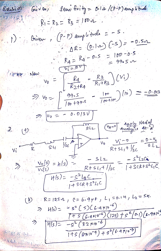
 A resistive temperature sensor Rv (calibration curve shown below) is used to measure the temperature of a process using Wheatstone bridge (Fig. 1). When the bridge is balanced, EO = OV. Then the Ry is inserted into a process whose temperature is 100C. Assume Ei = 10V, R1 = R2 = R3 = 4k12. 1. At which temperature the bridge is balanced? How much is EO at balanced mode? 2. Find the bridge output voltage E, a 3-significant figure voltmeter...
4. Analogue to digital converter (ADC) is one of the data processing. i. Describe the term quantization errot, sample af signal i ADK i. A 9 bits ADC is used in an electronic device for the mu...
 4. Analogue to digital converter (ADC) is one of the data processing. i. Describe the term quantization errot, sample af signal i ADK i. A 9 bits ADC is used in an electronic device for the murnt of analogue signal within the range of -TV to +TV. If an an measured as +3.2V, determine the value shows by the ADC (5 marks) The Wheatstone bridge circuit shown in the following figure is used to messure the resistance of a strain...
(05) mides Problem 1 (20%) In Figure 1 a balanced bridge circuit with resistors R,, R, R; and R, is shown. Vs are a...
 (05) mides Problem 1 (20%) In Figure 1 a balanced bridge circuit with resistors R,, R, R; and R, is shown. Vs are an ideal voltage source. R4 R3 ogi 1 itos lonoiesqo diw R. ten W tissbi sd itogns fkoinseno.cot tome o noiton oinoisej shov ts idgs ed Yorspet if 5den bnit sob woll ono oTo1 V t Figure 1. Balanced bridge circuit 1. Find the loading terminal of the circuit shown in Figure 1. 2. Find the Thevinin...
Hi could you please provide how to do problem 2? Amsterdam University of Applied Sciences Problem 2(15 points) A Wheatstone bridge is used to determine the resistance of a strain gauge. The 3 resista...
 Hi could you please provide how to do problem 2?
Amsterdam University of Applied Sciences Problem 2(15 points) A Wheatstone bridge is used to determine the resistance of a strain gauge. The 3 resistances R of the Wheatstone bridge are equal: R 200 12. When the strain gauge is fully relaxed (nd strain present), its resistance Rs is equal to the other 3 resistances: Rs-R. The strain is given bywith AR, the change in resistance in the strain gauge. The...
Hi could you please provide how to do problem 2?
Amsterdam University of Applied Sciences Problem 2(15 points) A Wheatstone bridge is used to determine the resistance of a strain gauge. The 3 resistances R of the Wheatstone bridge are equal: R 200 12. When the strain gauge is fully relaxed (nd strain present), its resistance Rs is equal to the other 3 resistances: Rs-R. The strain is given bywith AR, the change in resistance in the strain gauge. The...
Question 2: Conditioning CIPeuIL A. The circuit in Figure 1 is used to amplify the input...
 Question 2: Conditioning CIPeuIL A. The circuit in Figure 1 is used to amplify the input signal sh output waveform, labelling both the x and y axis (both numb and explain in detail why the signal has the shape it hass and labels) necessary calculations to support your answer. it has, including any 23ks2 +10V 2.3kΩ sin(10t)V10V Figure 1 B. The circuit in Figure 2 is a full ECG amplifier circuit. Page 2 of6 47 nF UA 1 k2 33...
Oil estion 2 (9%) The voltage output from a J-type thermocouple referenced 0°C is to be used to measure temperatures fr...
 Oil estion 2 (9%) The voltage output from a J-type thermocouple referenced 0°C is to be used to measure temperatures from 50 to 70°C. The output voltages vary linearly over this range from 2.585 to 3.649 mV 1. If the thermocouple voltage is input to a 12-bit A/D converter having a +5V range, estimate the percent quantization error in the digital value; 2. If the analog signal can be first passed through an amplifier circuit, compute the amplifier gain required...
8-4) Lathi & Ding, Prob. P.5.1-10 (a) A first-order-hold circuit can also be used to reconstruct ...
 .
8-4) Lathi & Ding, Prob. P.5.1-10 (a) A first-order-hold circuit can also be used to reconstruct a signal g) from its samples. The impulse response of this circuit is h(f) = Δ(2,-2) where Ts is the sampling interval. Consider a typical sampled signal R() and show that this circuit performs the linear interpolation. In other words, the filter output consists of sample tops connected by straight-line segments. Follow the procedure discussed in Sec. 5.1.2 (Fig. 5.6) for a typical...
.
8-4) Lathi & Ding, Prob. P.5.1-10 (a) A first-order-hold circuit can also be used to reconstruct a signal g) from its samples. The impulse response of this circuit is h(f) = Δ(2,-2) where Ts is the sampling interval. Consider a typical sampled signal R() and show that this circuit performs the linear interpolation. In other words, the filter output consists of sample tops connected by straight-line segments. Follow the procedure discussed in Sec. 5.1.2 (Fig. 5.6) for a typical...
The circuit shown in Figure Q4-1 includes an audio source and the equivalent circuit of a...
 The circuit shown in Figure Q4-1 includes an audio source and the equivalent circuit of a loudspeaker that you have been asked to analyse. 4. a) Assuming the speaker is to operate at a single frequency of 200 Hz and is5 driven by a cosinusoidal signal with peak amplitude of 20 V; determine the equivalent impedance of the speaker When connected to the audio source, calculate the current flow i() When testing the loudspeaker detailed in Q4a) i), you can...
6.108 (d) Section 6.5: Discrete-Circuit Amplifiers 6.107 Calculate overall voltage gain G, of a 3 mA/V, ro= = 1...
 6.108 (d)
Section 6.5: Discrete-Circuit Amplifiers 6.107 Calculate overall voltage gain G, of a 3 mA/V, ro= = 10 MS2. The amplifier is the common-source amplifier for which g 100 k2, RD 10 k2, and RG fed from a signal source with a Thevenin resistance of l M2, and the amplifier output is coupled of 20 k2 to a load resistance SIM 6.108 The NMOS transistor in the CS amplifier shown in Fig. P6.108 has V, = 0.7 V and...
6.108 (d)
Section 6.5: Discrete-Circuit Amplifiers 6.107 Calculate overall voltage gain G, of a 3 mA/V, ro= = 10 MS2. The amplifier is the common-source amplifier for which g 100 k2, RD 10 k2, and RG fed from a signal source with a Thevenin resistance of l M2, and the amplifier output is coupled of 20 k2 to a load resistance SIM 6.108 The NMOS transistor in the CS amplifier shown in Fig. P6.108 has V, = 0.7 V and...
 Filter A beam vibrates at 100 Hz. The vibrations are measured with a strain gage and Wheatstone bridge. The output voltage of the sensor is Vout = 2V s€, with Vs = 5.00 V the supply voltage and € = 8L/L the strain. The strain is in the range of +5 x 10⁻⁴. In addition, you know that: there is noise on the input: fnoise = 40,000Hz with amplitude 0.100 mV. The output is sent to your NI USB-6008 DAQ...
 A resistive temperature sensor Rv (calibration curve shown below) is used to measure the temperature of a process using Wheatstone bridge (Fig. 1). When the bridge is balanced, EO = OV. Then the Ry is inserted into a process whose temperature is 100C. Assume Ei = 10V, R1 = R2 = R3 = 4k12. 1. At which temperature the bridge is balanced? How much is EO at balanced mode? 2. Find the bridge output voltage E, a 3-significant figure voltmeter...
 4. Analogue to digital converter (ADC) is one of the data processing. i. Describe the term quantization errot, sample af signal i ADK i. A 9 bits ADC is used in an electronic device for the murnt of analogue signal within the range of -TV to +TV. If an an measured as +3.2V, determine the value shows by the ADC (5 marks) The Wheatstone bridge circuit shown in the following figure is used to messure the resistance of a strain...
 (05) mides Problem 1 (20%) In Figure 1 a balanced bridge circuit with resistors R,, R, R; and R, is shown. Vs are an ideal voltage source. R4 R3 ogi 1 itos lonoiesqo diw R. ten W tissbi sd itogns fkoinseno.cot tome o noiton oinoisej shov ts idgs ed Yorspet if 5den bnit sob woll ono oTo1 V t Figure 1. Balanced bridge circuit 1. Find the loading terminal of the circuit shown in Figure 1. 2. Find the Thevinin...
 Hi could you please provide how to do problem 2?
Amsterdam University of Applied Sciences Problem 2(15 points) A Wheatstone bridge is used to determine the resistance of a strain gauge. The 3 resistances R of the Wheatstone bridge are equal: R 200 12. When the strain gauge is fully relaxed (nd strain present), its resistance Rs is equal to the other 3 resistances: Rs-R. The strain is given bywith AR, the change in resistance in the strain gauge. The...
Hi could you please provide how to do problem 2?
Amsterdam University of Applied Sciences Problem 2(15 points) A Wheatstone bridge is used to determine the resistance of a strain gauge. The 3 resistances R of the Wheatstone bridge are equal: R 200 12. When the strain gauge is fully relaxed (nd strain present), its resistance Rs is equal to the other 3 resistances: Rs-R. The strain is given bywith AR, the change in resistance in the strain gauge. The...
 Question 2: Conditioning CIPeuIL A. The circuit in Figure 1 is used to amplify the input signal sh output waveform, labelling both the x and y axis (both numb and explain in detail why the signal has the shape it hass and labels) necessary calculations to support your answer. it has, including any 23ks2 +10V 2.3kΩ sin(10t)V10V Figure 1 B. The circuit in Figure 2 is a full ECG amplifier circuit. Page 2 of6 47 nF UA 1 k2 33...
 Oil estion 2 (9%) The voltage output from a J-type thermocouple referenced 0°C is to be used to measure temperatures from 50 to 70°C. The output voltages vary linearly over this range from 2.585 to 3.649 mV 1. If the thermocouple voltage is input to a 12-bit A/D converter having a +5V range, estimate the percent quantization error in the digital value; 2. If the analog signal can be first passed through an amplifier circuit, compute the amplifier gain required...
 .
8-4) Lathi & Ding, Prob. P.5.1-10 (a) A first-order-hold circuit can also be used to reconstruct a signal g) from its samples. The impulse response of this circuit is h(f) = Δ(2,-2) where Ts is the sampling interval. Consider a typical sampled signal R() and show that this circuit performs the linear interpolation. In other words, the filter output consists of sample tops connected by straight-line segments. Follow the procedure discussed in Sec. 5.1.2 (Fig. 5.6) for a typical...
.
8-4) Lathi & Ding, Prob. P.5.1-10 (a) A first-order-hold circuit can also be used to reconstruct a signal g) from its samples. The impulse response of this circuit is h(f) = Δ(2,-2) where Ts is the sampling interval. Consider a typical sampled signal R() and show that this circuit performs the linear interpolation. In other words, the filter output consists of sample tops connected by straight-line segments. Follow the procedure discussed in Sec. 5.1.2 (Fig. 5.6) for a typical...
 The circuit shown in Figure Q4-1 includes an audio source and the equivalent circuit of a loudspeaker that you have been asked to analyse. 4. a) Assuming the speaker is to operate at a single frequency of 200 Hz and is5 driven by a cosinusoidal signal with peak amplitude of 20 V; determine the equivalent impedance of the speaker When connected to the audio source, calculate the current flow i() When testing the loudspeaker detailed in Q4a) i), you can...
 6.108 (d)
Section 6.5: Discrete-Circuit Amplifiers 6.107 Calculate overall voltage gain G, of a 3 mA/V, ro= = 10 MS2. The amplifier is the common-source amplifier for which g 100 k2, RD 10 k2, and RG fed from a signal source with a Thevenin resistance of l M2, and the amplifier output is coupled of 20 k2 to a load resistance SIM 6.108 The NMOS transistor in the CS amplifier shown in Fig. P6.108 has V, = 0.7 V and...
6.108 (d)
Section 6.5: Discrete-Circuit Amplifiers 6.107 Calculate overall voltage gain G, of a 3 mA/V, ro= = 10 MS2. The amplifier is the common-source amplifier for which g 100 k2, RD 10 k2, and RG fed from a signal source with a Thevenin resistance of l M2, and the amplifier output is coupled of 20 k2 to a load resistance SIM 6.108 The NMOS transistor in the CS amplifier shown in Fig. P6.108 has V, = 0.7 V and...
Most questions answered within 3 hours.
-
C - Language
Write a loop that sets each array element to the sum of itself...
asked 53 minutes ago -
(63
#14)
which of the following statments best describes how chamging
the concentration of the substances...
asked 4 hours ago -
In the following reaction, which element is undergoing
oxidation: Na2SO3 + N2O --> N2 + Na2SO4...
asked 5 hours ago -
Which of the following pairs of ions have the same electron
configuration?
I: Br− and Se2−...
asked 7 hours ago -
The Foremost Composite Materials Company is planning a two-day
sales conference for October 19-20. The conference...
asked 8 hours ago -
3) Illustrate the observed pattern of relatedness of organisms
versus adaptations to specific conditions. This means...
asked 8 hours ago -
In winter a lake has a 0.35 m thick ice layer over 1.10 m of
water....
asked 9 hours ago -
Assuming the following has been encrypted with a Vigenere cipher
below, use the method(s) and assumptions...
asked 9 hours ago -
How would I use switch statements to write a program that will
take an input of...
asked 9 hours ago -
Imagine a reaction in which methane gas combusts at a constant
pressure of 1 atm and...
asked 9 hours ago -
Two parallel wires (each 12 m in length) are separated by a
distance of 0.065 m...
asked 9 hours ago -
Suppose there were three masses at the corner of uniform
equilateral triangle. The masses are m1...
asked 9 hours ago