
Homework Answers


Add Answer to:
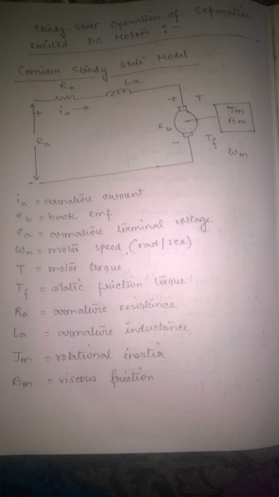
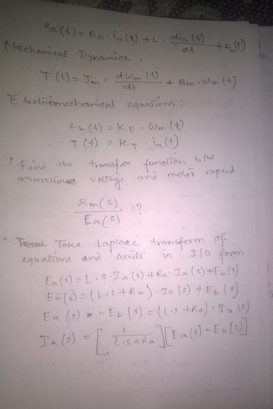
FQ5
4. Describe with aid of a block diagram the model for an rmature controlled DC...
The simplified diagram of a DC motor is shown in Fig. 4. Assume that the rotor has inertia m J an...
 The simplified diagram of a DC motor is shown in Fig. 4. Assume
that the rotor has inertia m J and viscous friction coefficient Bm.
The torque developed by the motor is assumed to be related linearly
to the field current by , m m f T K i where the motor torque
constant m f a K K K I 1 when the armature current a i is assumed
constant (i.e. ) a a i I...
The simplified diagram of a DC motor is shown in Fig. 4. Assume
that the rotor has inertia m J and viscous friction coefficient Bm.
The torque developed by the motor is assumed to be related linearly
to the field current by , m m f T K i where the motor torque
constant m f a K K K I 1 when the armature current a i is assumed
constant (i.e. ) a a i I...
QUESTION 4 AC VSD Sketch the block diagram of a scalar controlled induction motor vanable speed...
 QUESTION 4 AC VSD Sketch the block diagram of a scalar controlled induction motor vanable speed drve 41 (4) +21 Show that the Clarke transform is given by I,- (6) 4 2 Sketch the eight possible switching combinations for a three phase (8) [18 43 bridge inverter [TURN OVER
QUESTION 4 AC VSD Sketch the block diagram of a scalar controlled induction motor vanable speed drve 41 (4) +21 Show that the Clarke transform is given by I,- (6) 4...
QUESTION 4 AC VSD Sketch the block diagram of a scalar controlled induction motor vanable speed drve 41 (4) +21 Show that the Clarke transform is given by I,- (6) 4 2 Sketch the eight possible switching combinations for a three phase (8) [18 43 bridge inverter [TURN OVER
QUESTION 4 AC VSD Sketch the block diagram of a scalar controlled induction motor vanable speed drve 41 (4) +21 Show that the Clarke transform is given by I,- (6) 4...
The field coil controlled DC motor is shown schematically in Figure Q2. (a) Define all the...
 The field coil controlled DC motor is shown schematically in Figure Q2. (a) Define all the quantities shown on the Figure Q2 Q.2 (6 marks) Write down an expression which defines the motor torque in terms of currents. Reduce 4 marks) (b) this equation down into its simplest form, defining field control. (c) Show that the angular position of the motor is defined by θ(s) = Tm(s)-Ta(s) (5 marks) (d) By neglecting the disturbance torque proceed to show that the...
2. The block diagram below model a simple DC motor for speed control application. Input V(s)...
 2. The block diagram below model a simple DC motor for speed control application. Input V(s) is the desired speed in voltage, and the output Y(s) is the actual speed. Tachogenerator, H, convert the actual speed to corresponding voltage. Amplifier Motor and gears X() 5 Ls +R Tachogenerator H The following parameters are known about the system: Amplifier gain: A=2; Motor inductance: L=5H Tachogenerator gain: H=0.15; Determine the following: The system transfer function The value of the motor resistance, R,...
Analyze a DC series phase-controlled motor drive with single-phase, full wave, controlled AC/DC rectifier in continuous...
Analyze a DC series phase-controlled motor drive with single-phase, full wave, controlled AC/DC rectifier in continuous conduction mode (CCM) of operation. Draw the motor voltage and current waveforms and write the equations (instantaneous and averaged). Please note that the waveforms and equations have been presented in class for a DC separately-excited motor drive.
Draw ablock diagram illustrating the switched model of human speech production and briefly describe each block...
 Draw ablock diagram illustrating the switched model of human speech production and briefly describe each block What is wrong with this simple model? (c)
Draw ablock diagram illustrating the switched model of human speech production and briefly describe each block What is wrong with this simple model? (c)
Draw ablock diagram illustrating the switched model of human speech production and briefly describe each block What is wrong with this simple model? (c)
With the aid of a block diagram, show how an accelerometer can be used in the...
With the aid of a block diagram, show how an accelerometer can be used in the design of a measurement system. The block diagram should clearly show the sensing element, the required signal conditioning and signal processing elements.
In the figure below given is the block diagram representation of the DC motor position control sy...
 In the figure below given is the block diagram representation of the DC motor position control system with a combined unity feedback and rate (tachometer) feedback. 2. C(s) R(s) Kp 0.25s+1 s+1 Kv Determine the characteristic polynomial of the closed loop transfer function Using Routh criterion, determine the range for Kp and Kv which make the closed loop system stable. Draw the admissible region for stability on Kv versus Kp plane.
In the figure below given is the block diagram...
In the figure below given is the block diagram representation of the DC motor position control system with a combined unity feedback and rate (tachometer) feedback. 2. C(s) R(s) Kp 0.25s+1 s+1 Kv Determine the characteristic polynomial of the closed loop transfer function Using Routh criterion, determine the range for Kp and Kv which make the closed loop system stable. Draw the admissible region for stability on Kv versus Kp plane.
In the figure below given is the block diagram...
Draw a block diagram of the system shown below Figure P6.36 is the circuit diagram of...
 Draw a block diagram of the system shown below
Figure P6.36 is the circuit diagram of a speed-control system in which the dc motor voltage ua is supplied by a generator driven by an engine. This system has been used on locomotives whose diesel engine operates most efficiently at one speed. The efficiency of the electric motor is not as sensitive to speed and thus can be used to drive the locomotive at various speeds. The motor voltage va is...
Draw a block diagram of the system shown below
Figure P6.36 is the circuit diagram of a speed-control system in which the dc motor voltage ua is supplied by a generator driven by an engine. This system has been used on locomotives whose diesel engine operates most efficiently at one speed. The efficiency of the electric motor is not as sensitive to speed and thus can be used to drive the locomotive at various speeds. The motor voltage va is...
Describe Gauss’s Law with the aid of a clearly labeled diagram.
Describe Gauss’s Law with the aid of a clearly labeled diagram.
 The simplified diagram of a DC motor is shown in Fig. 4. Assume
that the rotor has inertia m J and viscous friction coefficient Bm.
The torque developed by the motor is assumed to be related linearly
to the field current by , m m f T K i where the motor torque
constant m f a K K K I 1 when the armature current a i is assumed
constant (i.e. ) a a i I...
The simplified diagram of a DC motor is shown in Fig. 4. Assume
that the rotor has inertia m J and viscous friction coefficient Bm.
The torque developed by the motor is assumed to be related linearly
to the field current by , m m f T K i where the motor torque
constant m f a K K K I 1 when the armature current a i is assumed
constant (i.e. ) a a i I...
 QUESTION 4 AC VSD Sketch the block diagram of a scalar controlled induction motor vanable speed drve 41 (4) +21 Show that the Clarke transform is given by I,- (6) 4 2 Sketch the eight possible switching combinations for a three phase (8) [18 43 bridge inverter [TURN OVER
QUESTION 4 AC VSD Sketch the block diagram of a scalar controlled induction motor vanable speed drve 41 (4) +21 Show that the Clarke transform is given by I,- (6) 4...
QUESTION 4 AC VSD Sketch the block diagram of a scalar controlled induction motor vanable speed drve 41 (4) +21 Show that the Clarke transform is given by I,- (6) 4 2 Sketch the eight possible switching combinations for a three phase (8) [18 43 bridge inverter [TURN OVER
QUESTION 4 AC VSD Sketch the block diagram of a scalar controlled induction motor vanable speed drve 41 (4) +21 Show that the Clarke transform is given by I,- (6) 4...
 The field coil controlled DC motor is shown schematically in Figure Q2. (a) Define all the quantities shown on the Figure Q2 Q.2 (6 marks) Write down an expression which defines the motor torque in terms of currents. Reduce 4 marks) (b) this equation down into its simplest form, defining field control. (c) Show that the angular position of the motor is defined by θ(s) = Tm(s)-Ta(s) (5 marks) (d) By neglecting the disturbance torque proceed to show that the...
 2. The block diagram below model a simple DC motor for speed control application. Input V(s) is the desired speed in voltage, and the output Y(s) is the actual speed. Tachogenerator, H, convert the actual speed to corresponding voltage. Amplifier Motor and gears X() 5 Ls +R Tachogenerator H The following parameters are known about the system: Amplifier gain: A=2; Motor inductance: L=5H Tachogenerator gain: H=0.15; Determine the following: The system transfer function The value of the motor resistance, R,...
 Draw ablock diagram illustrating the switched model of human speech production and briefly describe each block What is wrong with this simple model? (c)
Draw ablock diagram illustrating the switched model of human speech production and briefly describe each block What is wrong with this simple model? (c)
Draw ablock diagram illustrating the switched model of human speech production and briefly describe each block What is wrong with this simple model? (c)
 In the figure below given is the block diagram representation of the DC motor position control system with a combined unity feedback and rate (tachometer) feedback. 2. C(s) R(s) Kp 0.25s+1 s+1 Kv Determine the characteristic polynomial of the closed loop transfer function Using Routh criterion, determine the range for Kp and Kv which make the closed loop system stable. Draw the admissible region for stability on Kv versus Kp plane.
In the figure below given is the block diagram...
In the figure below given is the block diagram representation of the DC motor position control system with a combined unity feedback and rate (tachometer) feedback. 2. C(s) R(s) Kp 0.25s+1 s+1 Kv Determine the characteristic polynomial of the closed loop transfer function Using Routh criterion, determine the range for Kp and Kv which make the closed loop system stable. Draw the admissible region for stability on Kv versus Kp plane.
In the figure below given is the block diagram...
 Draw a block diagram of the system shown below
Figure P6.36 is the circuit diagram of a speed-control system in which the dc motor voltage ua is supplied by a generator driven by an engine. This system has been used on locomotives whose diesel engine operates most efficiently at one speed. The efficiency of the electric motor is not as sensitive to speed and thus can be used to drive the locomotive at various speeds. The motor voltage va is...
Draw a block diagram of the system shown below
Figure P6.36 is the circuit diagram of a speed-control system in which the dc motor voltage ua is supplied by a generator driven by an engine. This system has been used on locomotives whose diesel engine operates most efficiently at one speed. The efficiency of the electric motor is not as sensitive to speed and thus can be used to drive the locomotive at various speeds. The motor voltage va is...
Most questions answered within 3 hours.
-
. For this set of questions, determine what
proportion of a normal distribution is located betweeneach...
asked 7 minutes ago -
A college student is employed as a door-to-door newspaper
salesman. Historical data suggests that the student...
asked 1 hour ago -
MATLAB HW 11 problem using Switch Case and Input commands
Write a script file that calculates...
asked 47 minutes ago -
Considering gravitational time dilation, calculate the time that
passes in Earth’s surface while 1 hour passes...
asked 1 hour ago -
Minitab Problem: Take the Lake Hume June rainfall data and find
use the processes outlined in...
asked 2 hours ago -
X Company is trying to decide whether to continue using old
equipment to make Product A...
asked 2 hours ago -
IN PYTHON ONLY !! Program 2: Re-work
program #5 (WeeklyHours) from the previous assignment such that...
asked 2 hours ago -
The average length of time between arrivals at a turnpike
toll-booth is 26 seconds. What is...
asked 4 hours ago -
(a) A piston at 6.1 atm contains a gas that occupies a volume of
3.5 L....
asked 5 hours ago -
Please answer true or false. Words
cannot be changed or added in to make it true...
asked 5 hours ago -
An empty test tube weighs 15.923 grams. Then,
MgCl2•6H2O is added into the test tube. After...
asked 5 hours ago -
Assume memory access is 10 units of time and disk access is
10000 units of time....
asked 6 hours ago