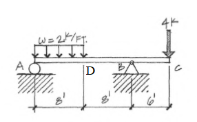
Problem #3
For the beam shown below,
- Determine the bending moments at A, B, C, and D. (MA, MB, MC, MD)
- Determine the maximum bending moment Mmax and its location.
- Determine the shear V at A, B , C, and D (VA, VB, VC, VD)
Homework Answers


Add Answer to:
Problem #3
For the beam shown below,
Determine the bending moments at A, B, C, and...
Problem l The beam shown below is laterally braced at D,F and F. The uniform load shown does not include the weight of the beam. Determine whether a W24x 104 ASTM A992 is adequate for bending and sh...
 Problem l The beam shown below is laterally braced at D,F and F. The uniform load shown does not include the weight of the beam. Determine whether a W24x 104 ASTM A992 is adequate for bending and shear. P,-12k PL -36k 3k/ft 10 20 30 FIGURE P5.5-15 a) Determine the controlling load combination and calculate Pu (for the concentrated force) and wu (for wo plus beam's selfweight, which is a uniformly distributed load) b) Analyze the beam loaded with the...
Shear force and bending moments of the beam. For the simply supported beam subjected to the...
 Shear force and bending moments of the beam.
For the simply supported beam subjected to the loading shown in Figure P7.8 derive equations for the shear force V and the bending moment M for any location in the beam. (Place the origin at point A.) plot the shear-force and bending-moment diagrams for the beam, using the derived functions. report the maximum positive bending moment, the maximum negative bending moment, and their respective locations.
Shear force and bending moments of the beam.
For the simply supported beam subjected to the loading shown in Figure P7.8 derive equations for the shear force V and the bending moment M for any location in the beam. (Place the origin at point A.) plot the shear-force and bending-moment diagrams for the beam, using the derived functions. report the maximum positive bending moment, the maximum negative bending moment, and their respective locations.
Use the graphical method to construct the shear-force and bending-moment diagrams for the beam shown.
 Use the graphical method to construct the shear-force and bending-moment diagrams for the beam shown. Label all significant points on each diagram and identify the maximum moments along with their respective locations. For all answers entered, use the sign convention for shear forces and bending moments. (a) Find the location x and the corresponding bending moment M at the one point between A and B at which the shear force equals zero. (b) Consider the entire beam and determine the maximum positive...
Use the graphical method to construct the shear-force and bending-moment diagrams for the beam shown. Label...
 Use the graphical method to construct the shear-force and bending-moment diagrams for the beam shown. Label all significant points on each diagram and identify the maximum moments along with their respective locations. For all answers entered, use the sign convention for shear forces and bending moments (a) Find the location x and the corresponding bending moment M at the one point between A and D at which the shear force equals zero. (b) Consider the entire beam and determine the...
PROBLEM 5.53 w=w0(1-1/2 Determine (a) the equations of the shear and bending-moment curves for the beam...
 PROBLEM 5.53 w=w0(1-1/2 Determine (a) the equations of the shear and bending-moment curves for the beam and loading shown, (b) the maximum absolute value of the bending moment in the beam. Answ: V(x) = -W. (x-x?/2L- L/3); M(x) = wo (x3/6L – x²/2 +Lx/3); Mmax = 0.0642wol?
To determine the reactive forces and moments acting on a beam;express the shear and bending...
 To determine the reactive forces and moments acting on a beam;
express the shear and bending moment as functions of their
positions along the beam; and construct shear and bending moment
diagrams. The cantilever beam shown is subjected to a moment at A
and a distributed load that acts over segment BC, and is fixed at
C. Determine the reactions at the support located at C. Then write
expressions for shear and bending moment as a function of their
positions...
To determine the reactive forces and moments acting on a beam;
express the shear and bending moment as functions of their
positions along the beam; and construct shear and bending moment
diagrams. The cantilever beam shown is subjected to a moment at A
and a distributed load that acts over segment BC, and is fixed at
C. Determine the reactions at the support located at C. Then write
expressions for shear and bending moment as a function of their
positions...
For the beam and loading shown, (a) draw the shear and bending- moment diagrams, (b) determine the magnitude and location of the maximum absolute value of the bending moment.
 PROBLEM 7.81 For the beam and loading shown, (a) draw the shear and bending- moment diagrams, (b) determine the magnitude and location of the maximum absolute value of the bending moment.
(a) Find the location x and the corresponding bending moment M at the one point between...
 (a) Find the location x and the corresponding bending moment M at the one point between A and B at which the shear force equals zero. (b) Consider the entire beam and determine the maximum positive bending moment. (c) Consider the entire beam and determine the negative bending moment with the largest absolute value. Use the bending moment sign convention, so enter a negative value Additionally (d) Determine V and M in the beam at a point located 0.75 m...
Need help Question 6 For the beam shown below, 2.0 Determine the shear V at A,...
 Need help
Question 6 For the beam shown below, 2.0 Determine the shear V at A, B, and C (VA, VB, Vc) CAVA-30, VB =-15, VC-45 OB. VA -30, VB -15, Vc 45 VC = 45 VC. =45 c.Ya-30, VB-15, -D.VA-30, VB -15,
Need help
Question 6 For the beam shown below, 2.0 Determine the shear V at A, B, and C (VA, VB, Vc) CAVA-30, VB =-15, VC-45 OB. VA -30, VB -15, Vc 45 VC = 45 VC. =45 c.Ya-30, VB-15, -D.VA-30, VB -15,
Problem 4: For the fixed-fixed beam shown below, a) Sketch the shear force and bending moment...
 Problem 4: For the fixed-fixed beam shown below, a) Sketch the shear force and bending moment diagrams. Consider P1 = 10 kips, P2 = 15 kips, and w = 2 kips/ft. b) Indicate the values of maximum positive and negative bending moments and specify the location of these maximum values along the beam. (You are allowed to refer to the attached AISC Table for appropriate formulations or use any software) P2 TTTTTTTTTTTTTTT 6 ft. 1 0ft. t 4 ft.
 Problem l The beam shown below is laterally braced at D,F and F. The uniform load shown does not include the weight of the beam. Determine whether a W24x 104 ASTM A992 is adequate for bending and shear. P,-12k PL -36k 3k/ft 10 20 30 FIGURE P5.5-15 a) Determine the controlling load combination and calculate Pu (for the concentrated force) and wu (for wo plus beam's selfweight, which is a uniformly distributed load) b) Analyze the beam loaded with the...
 Shear force and bending moments of the beam.
For the simply supported beam subjected to the loading shown in Figure P7.8 derive equations for the shear force V and the bending moment M for any location in the beam. (Place the origin at point A.) plot the shear-force and bending-moment diagrams for the beam, using the derived functions. report the maximum positive bending moment, the maximum negative bending moment, and their respective locations.
Shear force and bending moments of the beam.
For the simply supported beam subjected to the loading shown in Figure P7.8 derive equations for the shear force V and the bending moment M for any location in the beam. (Place the origin at point A.) plot the shear-force and bending-moment diagrams for the beam, using the derived functions. report the maximum positive bending moment, the maximum negative bending moment, and their respective locations.
 Use the graphical method to construct the shear-force and bending-moment diagrams for the beam shown. Label all significant points on each diagram and identify the maximum moments along with their respective locations. For all answers entered, use the sign convention for shear forces and bending moments. (a) Find the location x and the corresponding bending moment M at the one point between A and B at which the shear force equals zero. (b) Consider the entire beam and determine the maximum positive...
 Use the graphical method to construct the shear-force and bending-moment diagrams for the beam shown. Label all significant points on each diagram and identify the maximum moments along with their respective locations. For all answers entered, use the sign convention for shear forces and bending moments (a) Find the location x and the corresponding bending moment M at the one point between A and D at which the shear force equals zero. (b) Consider the entire beam and determine the...
 PROBLEM 5.53 w=w0(1-1/2 Determine (a) the equations of the shear and bending-moment curves for the beam and loading shown, (b) the maximum absolute value of the bending moment in the beam. Answ: V(x) = -W. (x-x?/2L- L/3); M(x) = wo (x3/6L – x²/2 +Lx/3); Mmax = 0.0642wol?
 To determine the reactive forces and moments acting on a beam;
express the shear and bending moment as functions of their
positions along the beam; and construct shear and bending moment
diagrams. The cantilever beam shown is subjected to a moment at A
and a distributed load that acts over segment BC, and is fixed at
C. Determine the reactions at the support located at C. Then write
expressions for shear and bending moment as a function of their
positions...
To determine the reactive forces and moments acting on a beam;
express the shear and bending moment as functions of their
positions along the beam; and construct shear and bending moment
diagrams. The cantilever beam shown is subjected to a moment at A
and a distributed load that acts over segment BC, and is fixed at
C. Determine the reactions at the support located at C. Then write
expressions for shear and bending moment as a function of their
positions...
 (a) Find the location x and the corresponding bending moment M at the one point between A and B at which the shear force equals zero. (b) Consider the entire beam and determine the maximum positive bending moment. (c) Consider the entire beam and determine the negative bending moment with the largest absolute value. Use the bending moment sign convention, so enter a negative value Additionally (d) Determine V and M in the beam at a point located 0.75 m...
 Need help
Question 6 For the beam shown below, 2.0 Determine the shear V at A, B, and C (VA, VB, Vc) CAVA-30, VB =-15, VC-45 OB. VA -30, VB -15, Vc 45 VC = 45 VC. =45 c.Ya-30, VB-15, -D.VA-30, VB -15,
Need help
Question 6 For the beam shown below, 2.0 Determine the shear V at A, B, and C (VA, VB, Vc) CAVA-30, VB =-15, VC-45 OB. VA -30, VB -15, Vc 45 VC = 45 VC. =45 c.Ya-30, VB-15, -D.VA-30, VB -15,
 Problem 4: For the fixed-fixed beam shown below, a) Sketch the shear force and bending moment diagrams. Consider P1 = 10 kips, P2 = 15 kips, and w = 2 kips/ft. b) Indicate the values of maximum positive and negative bending moments and specify the location of these maximum values along the beam. (You are allowed to refer to the attached AISC Table for appropriate formulations or use any software) P2 TTTTTTTTTTTTTTT 6 ft. 1 0ft. t 4 ft.
Most questions answered within 3 hours.
-
A χ2-curve, looking at the relationship between age and hours
spent working at an office per...
asked 14 minutes ago -
The pH of a sample of water from a river is 5.0. A
sample of effluent from...
asked 59 minutes ago -
At the beginning of the period, the Fabricating Department
budgeted direct labor of $136,500 and equipment...
asked 1 hour ago -
Please answer all
____ 28. Rent control is usually
justified on the grounds that it protects...
asked 1 hour ago -
PARTS A-D HAVE BEEN ANSWERED. WAS TOLD TO REPOST. ONLY ANSWER
PARTS E and F.
A...
asked 1 hour ago -
2) You are given the task of finding a representation for a
circle in a drawing...
asked 2 hours ago -
STUDY QUESTION: Does use of diet drug fen-phen
(fenfluramine-phentermine) cause valvular heart disease?
HINT: Valvular heart...
asked 2 hours ago -
1. An object weighing 40 N rests on a surface. The coefficient
of friction is 0.35....
asked 4 hours ago -
Investor company owns 35% of investee company voting stock and
accounts for the investment under the...
asked 5 hours ago -
The number of major faults on a randomly chosen 1 km stretch of
highway has a...
asked 5 hours ago -
Consider the competitive environment of Starbuck's, Progressive
Insurance, a manufacturing firm with low turnover, or a...
asked 6 hours ago -
3. Gains from trade
Consider two neighbouring island countries called Euphoria and
Contente. They each have...
asked 8 hours ago