Draw a circuit to interface the output of a two-wire NO proximity sensor that uses a...
Draw a circuit to interface the output of a two-wire NO proximity sensor that uses a 24 VDC power supply to the digital input line of an MCU that operates with VDD of 5 V.
Homework Answers
Hi,
There are many ways to interface a normally-open (NO) proximity sensor to a 5V MCU. The safest of these is to use an optocoupler IC in-between. An opto-coupler is an LED and phototransistor packaged inside an IC. The following image shows this circuit. The computation for the resistance is series with LED (to control the amount of current that flows through it) is also shown.
Note than when NO contact is open, the LED will off and hence the voltage at the output of phototransistor will be high. When the contact closes, a current of about 10mA will flow through the LED, turning it on. At that time, the output of phototransistor will go low.
The value of R2 is not very critical. It can be in the range of 2K to 10K for a typical optocoupler.
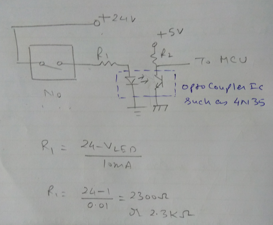
An additional advantage of using an optocoupler is that it keeps the grounds of 24V power supply and 5V power supply separate.
Hope this helps.
Add Answer to:
Draw a circuit to interface the output of a two-wire NO
proximity sensor that uses a...
Draw a circuit to output the following wave as 1V pk-pk sine wave centered at 0V and output to be...
 Draw a circuit to output the following wave as 1V
pk-pk sine wave centered at 0V and output to be out of phase
180degrees with respect to input.
Problem #5 [10 points]: Design a circuit with the following criteria. Assume existence of +5V power supply. Draw your circuit and show your work. i. Input signal that operates between Vin -5V- +5V, and capable of sourcing or sinking 500 x 10^-6 A. ii. Output signal nominally outputs between Vout 0V 5V,...
Draw a circuit to output the following wave as 1V
pk-pk sine wave centered at 0V and output to be out of phase
180degrees with respect to input.
Problem #5 [10 points]: Design a circuit with the following criteria. Assume existence of +5V power supply. Draw your circuit and show your work. i. Input signal that operates between Vin -5V- +5V, and capable of sourcing or sinking 500 x 10^-6 A. ii. Output signal nominally outputs between Vout 0V 5V,...
R Problem 4 (15 points): The output of an infrared distance sensor (with zero output impedance)...
 R Problem 4 (15 points): The output of an infrared distance sensor (with zero output impedance) varies from O to 5 V linearly as the distance of an object from the sensor changes from 0 to 100 cm. The output of the sensor is connected to the input of the circuit shown on the right (where the op amp has supply voltages +2 V and -2 V, and R = 1 ks). If you want this entire system to measure...
QUESTION 5 (15 points) a. You have a power supply which is a full-wave rectifier with a capacitor filter It operates fr...
 QUESTION 5 (15 points) a. You have a power supply which is a full-wave rectifier with a capacitor filter It operates from the mains and provides an output of Voc-: 20 V with 20% ripple, when the load current is 2 A. Calculate the maximum and minimum values of the output waveform of this power supply. b. Now you will design a series voltage regulator between the power supply described in part (a) and an electronic device operating at 12...
QUESTION 5 (15 points) a. You have a power supply which is a full-wave rectifier with a capacitor filter. It operates f...
 QUESTION 5 (15 points) a. You have a power supply which is a full-wave rectifier with a capacitor filter. It operates from the mains and provides an output of Voc-20 V with 20% ripple, when the load current is 2 A Calculate the maximum and minimum values of the output waveform of this power supply. b. Now you will design a series voltage regulator between the power supply described in part (a) and an electronic device operating at 12 VDC...
Problem #5 [10 points]: Design a circuit with the following criteria. Assume existence of +5V pow...
 Problem #5 [10 points]: Design a circuit with the following criteria. Assume existence of +5V power supply. Draw your circuit and show your work. i. Input signal that operates between Vin -5V- +5V, and capable of sourcing or sinking 500 x 10^-6 A. ii. Output signal nominally outputs between Vout 0V 5V, and capable of sinking 1 mA from an external device with an output no more than 0.1 V
Problem #5 [10 points]: Design a circuit with the following...
Problem #5 [10 points]: Design a circuit with the following criteria. Assume existence of +5V power supply. Draw your circuit and show your work. i. Input signal that operates between Vin -5V- +5V, and capable of sourcing or sinking 500 x 10^-6 A. ii. Output signal nominally outputs between Vout 0V 5V, and capable of sinking 1 mA from an external device with an output no more than 0.1 V
Problem #5 [10 points]: Design a circuit with the following...
The circuit 3-The circuit of problem # 2 is subjected to a small ac input by the signal generator. By neglecting the voltage drop across the coupling and bypass capacitors, determine the small signa...
 The circuit
3-The circuit of problem # 2 is subjected to a small ac input by the signal generator. By neglecting the voltage drop across the coupling and bypass capacitors, determine the small signal voltage gain Vo/ Vì = Avi , input resistance Ri-vi / ii and the output resistance Ro external to R Avi= Ri= , Ro The accompanying circuit shows a 4-resistor biased JFET transistor Determine the values of Rp and Rs so that the Q-point is equal...
The circuit
3-The circuit of problem # 2 is subjected to a small ac input by the signal generator. By neglecting the voltage drop across the coupling and bypass capacitors, determine the small signal voltage gain Vo/ Vì = Avi , input resistance Ri-vi / ii and the output resistance Ro external to R Avi= Ri= , Ro The accompanying circuit shows a 4-resistor biased JFET transistor Determine the values of Rp and Rs so that the Q-point is equal...
(20 points) Give a detail design of pressure measurement system by using strain gage as a sensor. The output signal is voltage 1) Draw circuit diagram/and sensing element with strain gauge. 2) Dr...
 (20 points) Give a detail design of pressure measurement system by using strain gage as a sensor. The output signal is voltage 1) Draw circuit diagram/and sensing element with strain gauge. 2) Draw a block diagram and name a part on each block. 3) Give the sensitivity of each block 4) Give an equation to show the relationship of input pressure and output 2. voltage
(20 points) Give a detail design of pressure measurement system by using strain gage as...
(20 points) Give a detail design of pressure measurement system by using strain gage as a sensor. The output signal is voltage 1) Draw circuit diagram/and sensing element with strain gauge. 2) Draw a block diagram and name a part on each block. 3) Give the sensitivity of each block 4) Give an equation to show the relationship of input pressure and output 2. voltage
(20 points) Give a detail design of pressure measurement system by using strain gage as...
3. Two sensors are mounted on a half-white rotating disk as shown below. Sensor output is...
 3. Two sensors are mounted on a half-white rotating disk as shown below. Sensor output is 5V for white and 0V for dark. Specify the digital element or elements to put in the black box so that the LED is ON for clockwise rotation. (Hint: Look at the waveforms and include D flip-flops only.) +5 V BO
10. Draw below a schematic of an inverting op amp circuit operating from a single +voltage DC supply, that has a gain from input to output Av = 5 WITHOUT DISTORTION, with a 1kΩ load resistor. The inpu...
10. Draw below a schematic of an inverting op amp circuit operating from a single +voltage DC supply, that has a gain from input to output Av = 5 WITHOUT DISTORTION, with a 1kΩ load resistor. The input will be a 500mVRMS sinewave. BE SURE TO SHOW ALL POWER AND GROUND connections and POWER VOLTAGE LEVELS. Use Esupply = +20V, and assume 1 V headrooms.
Draw a combinational logic circuit that implements a four-channel multiplexer which uses two input lines to...
Draw a combinational logic circuit that implements a four-channel multiplexer which uses two input lines to select the input channel to be connected to the output.
 Draw a circuit to output the following wave as 1V
pk-pk sine wave centered at 0V and output to be out of phase
180degrees with respect to input.
Problem #5 [10 points]: Design a circuit with the following criteria. Assume existence of +5V power supply. Draw your circuit and show your work. i. Input signal that operates between Vin -5V- +5V, and capable of sourcing or sinking 500 x 10^-6 A. ii. Output signal nominally outputs between Vout 0V 5V,...
Draw a circuit to output the following wave as 1V
pk-pk sine wave centered at 0V and output to be out of phase
180degrees with respect to input.
Problem #5 [10 points]: Design a circuit with the following criteria. Assume existence of +5V power supply. Draw your circuit and show your work. i. Input signal that operates between Vin -5V- +5V, and capable of sourcing or sinking 500 x 10^-6 A. ii. Output signal nominally outputs between Vout 0V 5V,...
 R Problem 4 (15 points): The output of an infrared distance sensor (with zero output impedance) varies from O to 5 V linearly as the distance of an object from the sensor changes from 0 to 100 cm. The output of the sensor is connected to the input of the circuit shown on the right (where the op amp has supply voltages +2 V and -2 V, and R = 1 ks). If you want this entire system to measure...
 QUESTION 5 (15 points) a. You have a power supply which is a full-wave rectifier with a capacitor filter It operates from the mains and provides an output of Voc-: 20 V with 20% ripple, when the load current is 2 A. Calculate the maximum and minimum values of the output waveform of this power supply. b. Now you will design a series voltage regulator between the power supply described in part (a) and an electronic device operating at 12...
 QUESTION 5 (15 points) a. You have a power supply which is a full-wave rectifier with a capacitor filter. It operates from the mains and provides an output of Voc-20 V with 20% ripple, when the load current is 2 A Calculate the maximum and minimum values of the output waveform of this power supply. b. Now you will design a series voltage regulator between the power supply described in part (a) and an electronic device operating at 12 VDC...
 Problem #5 [10 points]: Design a circuit with the following criteria. Assume existence of +5V power supply. Draw your circuit and show your work. i. Input signal that operates between Vin -5V- +5V, and capable of sourcing or sinking 500 x 10^-6 A. ii. Output signal nominally outputs between Vout 0V 5V, and capable of sinking 1 mA from an external device with an output no more than 0.1 V
Problem #5 [10 points]: Design a circuit with the following...
Problem #5 [10 points]: Design a circuit with the following criteria. Assume existence of +5V power supply. Draw your circuit and show your work. i. Input signal that operates between Vin -5V- +5V, and capable of sourcing or sinking 500 x 10^-6 A. ii. Output signal nominally outputs between Vout 0V 5V, and capable of sinking 1 mA from an external device with an output no more than 0.1 V
Problem #5 [10 points]: Design a circuit with the following...
 The circuit
3-The circuit of problem # 2 is subjected to a small ac input by the signal generator. By neglecting the voltage drop across the coupling and bypass capacitors, determine the small signal voltage gain Vo/ Vì = Avi , input resistance Ri-vi / ii and the output resistance Ro external to R Avi= Ri= , Ro The accompanying circuit shows a 4-resistor biased JFET transistor Determine the values of Rp and Rs so that the Q-point is equal...
The circuit
3-The circuit of problem # 2 is subjected to a small ac input by the signal generator. By neglecting the voltage drop across the coupling and bypass capacitors, determine the small signal voltage gain Vo/ Vì = Avi , input resistance Ri-vi / ii and the output resistance Ro external to R Avi= Ri= , Ro The accompanying circuit shows a 4-resistor biased JFET transistor Determine the values of Rp and Rs so that the Q-point is equal...
 (20 points) Give a detail design of pressure measurement system by using strain gage as a sensor. The output signal is voltage 1) Draw circuit diagram/and sensing element with strain gauge. 2) Draw a block diagram and name a part on each block. 3) Give the sensitivity of each block 4) Give an equation to show the relationship of input pressure and output 2. voltage
(20 points) Give a detail design of pressure measurement system by using strain gage as...
(20 points) Give a detail design of pressure measurement system by using strain gage as a sensor. The output signal is voltage 1) Draw circuit diagram/and sensing element with strain gauge. 2) Draw a block diagram and name a part on each block. 3) Give the sensitivity of each block 4) Give an equation to show the relationship of input pressure and output 2. voltage
(20 points) Give a detail design of pressure measurement system by using strain gage as...
 3. Two sensors are mounted on a half-white rotating disk as shown below. Sensor output is 5V for white and 0V for dark. Specify the digital element or elements to put in the black box so that the LED is ON for clockwise rotation. (Hint: Look at the waveforms and include D flip-flops only.) +5 V BO
Most questions answered within 3 hours.
-
you plan on savings $500 per month for 30 years and invest each
of those payments...
asked 1 hour ago -
1. Kenny Inc. has the following income statement for the most
recent fiscal year:
Sales $558.400...
asked 58 minutes ago -
A meter stick is found to balance at the 45.8 cm mark when
placed on a...
asked 1 hour ago -
1. A manufacturer of processing chips knows that 2% of its chips
are defective in some...
asked 4 hours ago -
Discuss what you think the exit polls tell us about voters.
asked 4 hours ago -
The electron in a hydrogen atom can undergo a transition from
n=1 to n=6, absorbing a...
asked 5 hours ago -
Based on what you learned in chapter 11, why would an
individual with a high BMI...
asked 5 hours ago -
Assume the economy can be described by the consumption function
C = $300 billion + 0.9Y...
asked 5 hours ago -
Within an environment where change is needed, you must recognize
the obstacles that can make changes...
asked 5 hours ago -
Travelcraft, Inc., manufactures a complete line of fiberglass
suitcases and attaché cases. The firm has...
asked 5 hours ago -
1a.
During 2021, a company sells 270 units of inventory for $94
each. The company has...
asked 5 hours ago -
A 7.3 kg ladder, 1.92 m long, rests on two sawhorses, as shown
in Figure 20....
asked 5 hours ago