Need help with Multisim to simulate these circuit diagrams. Any Multisim works, preferrably Multisim Live
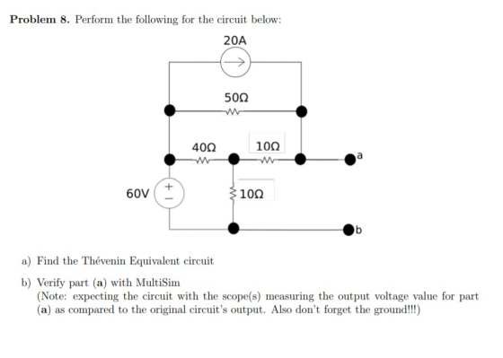
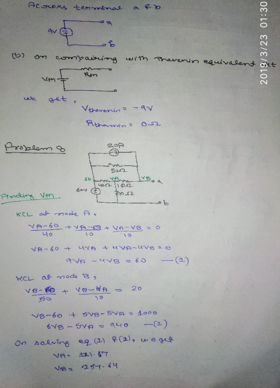
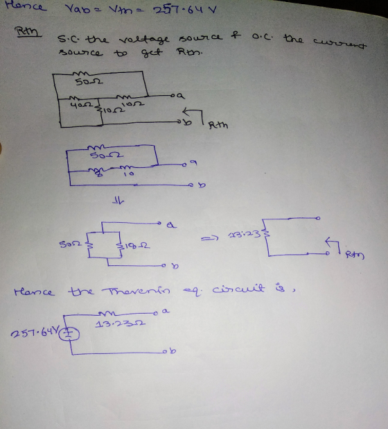
Problem 8. Perform the following for the circuit below 20A 500 40Ω 10Ω 60V 10Ω a) Find the Thévenin Equivalent circuit b) Verify part (a) with MultiSim (Note: expecting the circuit with the scope(s) measuring the output voltage value for part (a) as compared to the original circuit's output. Also don't forget the ground!!)
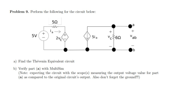
Problem 9. Perform the following for the circuit below: 5i 6 ab a) Find the Thévenin Equivalent circuit b) Verify part (a) with MultiSim (Note: expecting the circuit with the scope(s) measuring the output voltage value for part (a) as compared to the original circuit's output. Also don't forget the ground!!!)
Homework Answers
Add Answer to:
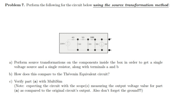
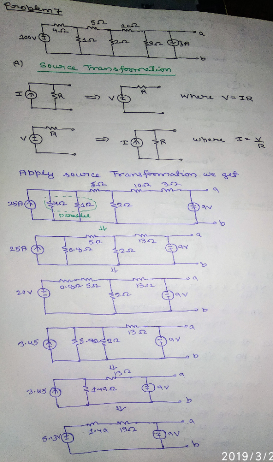
Problem 7. Perform the following for the circuit below using the source transformation method 40 ...
Need help with Multisim to simulate these circuit diagrams. Any Multisim works, preferrably Multisim Live Problem...
 Need help with Multisim to simulate these circuit diagrams. Any
Multisim works, preferrably Multisim Live
Problem 7. Perform the following for the circuit below using the source transformation method 40 5Ω 10Ω 100V 1Ω 20 30 3A a) Perform source transformations on the components inside the box in order to get a single voltage source and a single resistor, along with terminals a and b b) How does this compare to the Thévenin Equivalent circuit? c) Verify part (a) with...
Need help with Multisim to simulate these circuit diagrams. Any
Multisim works, preferrably Multisim Live
Problem 7. Perform the following for the circuit below using the source transformation method 40 5Ω 10Ω 100V 1Ω 20 30 3A a) Perform source transformations on the components inside the box in order to get a single voltage source and a single resistor, along with terminals a and b b) How does this compare to the Thévenin Equivalent circuit? c) Verify part (a) with...
Problem 1. Perform the following for the circuit below using the node voltage method: 10Ω 10Ω...
 Problem 1. Perform the following for the circuit below using the node voltage method: 10Ω 10Ω 5i a) Calculate ia b) Calculate v c) Calculate Psource,5ia Problem 2. Perform the following for the circuit below using the node voltage method: 10Ω 1 4Ω 2 60V+ 30A V. 3 2Ω 5Ω 3 a) Calculate vi, v2 and vs b) Calculate Psource 30A c) Calculate Psource,Gov node voltage method Problem 3. Perform the following for the circuit below using the 10V 4Ω...
Ch4 Problem 4.67 4 of 7 Part A Find the equivalent voltage. Express your answer to...
 Ch4 Problem 4.67 4 of 7 Part A Find the equivalent voltage. Express your answer to three significant figures and include the Find the Thévenin equivalent with respect to the terminals a b for the circuit in (Figure 1) if v-360 V, appropriate units. Units Figure < 1011 > Part B 150 2 Find the equivalent resistance. 10Ω Express your answer to three significant figures and include the appropriate units. 40Ω 8 0 RValue
7. (40 POINTS) An LRC series circuit is driven by a voltage source ε.coset, where ε,-10.0...
 7. (40 POINTS) An LRC series circuit is driven by a voltage source ε.coset, where ε,-10.0 V. R 140.0 ohms and C-1.0 μF. Note: 1.0 μF-10. 6 F. The circuit's resonant frequency is co- 6.28 x 10 3 rad/s. (a) (5) If the resistor value R is doubled, would the resonant frequency change? Yes or No Circle one. EXPLAIN (b) (5) What is the inductance L? (c) (5) If the voltage source frequency ω = ω then what is the...
Determine the voltage across resistor R2=40ΩR2=40Ω in the circuit shown in (Figure 1), where vs=60Vvs=60V, R1=20ΩR1=20Ω,...
 Determine the voltage across resistor R2=40ΩR2=40Ω in the
circuit shown in (Figure 1), where vs=60Vvs=60V, R1=20ΩR1=20Ω,
R3=30ΩR3=30Ω, and R4=40Ω
Question 6 Part A Determine the voltage across resistor R2 = 40 2 in the circuit shown in (Figure 1), where us = 60 V, R1 = 20 12 R3 = 30 12, and R4 = 40 12 Express your answer in volts to three significant figures. View Available Hint(s) Learning Goal: To determine the voltage, current, and power of circuit...
Determine the voltage across resistor R2=40ΩR2=40Ω in the
circuit shown in (Figure 1), where vs=60Vvs=60V, R1=20ΩR1=20Ω,
R3=30ΩR3=30Ω, and R4=40Ω
Question 6 Part A Determine the voltage across resistor R2 = 40 2 in the circuit shown in (Figure 1), where us = 60 V, R1 = 20 12 R3 = 30 12, and R4 = 40 12 Express your answer in volts to three significant figures. View Available Hint(s) Learning Goal: To determine the voltage, current, and power of circuit...
Problem: (1) For the single phase AC circuit shown below, calculate voltage phasor across the loa...
 Problem: (1) For the single phase AC circuit shown below, calculate voltage phasor across the load showing amplitude and phase angle for a (reference) source voltage of 220 V and 0 degree. Also, attach your MultiSIM simulation showing the voltage amplitude across the load. Compare simulated and calculated values. Load Bus of an Industrial Facility (equivalent of Electrical Motors and power factor correction Cap in parallel). R1 L1 Vload-? 1 3.0ohm 2 10mH 3 4.7mH 4 20ohm R2 +220V, 60...
Lab Procedure: Part 1: Source Free RC Circuit V(t) ilts C3 (R3 21ko 1uF IC=10V a)...
 Lab Procedure: Part 1: Source Free RC Circuit V(t) ilts C3 (R3 21ko 1uF IC=10V a) For the circuit shown above, provide the equation and calculate the following: 1. The source free equation for V(t) for V(O)= 10 volts 2. The equation for it) 3. V(t) and i(t) for t = t (one time constant) b) Now, enter the circuit using Multisim Schematic Capture. c) Simulate using Transient mode with a graphical output and verify graphical results with your calculations....
A MOSFET is wired as a common-source amplifier as shown below. The input voltage vIN is...
 A MOSFET is wired as a common-source amplifier as shown below.
The input voltage vIN is the total of the source for
biasing the circuit at its operating point (vBIAS), and
a small signal ac source providing the signal that we want to
amplify (vin). The total output voltage is
vO.
a) Assume VDD = 5?, VIN = 2?, and ? = 4?Ω
in the circuit and the MOSFET parameters are K =
0.5??/?2, VTH 1?, and ? = 0.05V-1....
A MOSFET is wired as a common-source amplifier as shown below.
The input voltage vIN is the total of the source for
biasing the circuit at its operating point (vBIAS), and
a small signal ac source providing the signal that we want to
amplify (vin). The total output voltage is
vO.
a) Assume VDD = 5?, VIN = 2?, and ? = 4?Ω
in the circuit and the MOSFET parameters are K =
0.5??/?2, VTH 1?, and ? = 0.05V-1....
2. In the circuit below, R1 = 10k, R2 : magnitude is applied to the input....
 2. In the circuit below, R1 = 10k, R2 : magnitude is applied to the input. Find V(t) at the output and sketch it. Your sketch should be quantitatively correct, that is, it should have labeled V and t axes. Strongly suggested: solve by first finding the Thévenin equivalent of the source voltage and resistor network. 20k and C = 0.1µF. At t = 0, a step function of 10 V Input (problem 3) R, 10V- IN R2 C, OUT...
Problem #7) Perform a steady-state AC phasor analysis of the circuit shown below in order to...
 Problem #7) Perform a steady-state AC phasor analysis of the circuit shown below in order to determine the RMS phasor values of the source current I, and the resistor voltage V, as shown in the figure, along with the value of the reactive power Qs produced by the voltage source: He v(t)=2.277-sin(0-t) 0=27. f ſ 60F f = 60 Hz vo 210 mH3 son Qs - - VARS
 Need help with Multisim to simulate these circuit diagrams. Any
Multisim works, preferrably Multisim Live
Problem 7. Perform the following for the circuit below using the source transformation method 40 5Ω 10Ω 100V 1Ω 20 30 3A a) Perform source transformations on the components inside the box in order to get a single voltage source and a single resistor, along with terminals a and b b) How does this compare to the Thévenin Equivalent circuit? c) Verify part (a) with...
Need help with Multisim to simulate these circuit diagrams. Any
Multisim works, preferrably Multisim Live
Problem 7. Perform the following for the circuit below using the source transformation method 40 5Ω 10Ω 100V 1Ω 20 30 3A a) Perform source transformations on the components inside the box in order to get a single voltage source and a single resistor, along with terminals a and b b) How does this compare to the Thévenin Equivalent circuit? c) Verify part (a) with...
 Problem 1. Perform the following for the circuit below using the node voltage method: 10Ω 10Ω 5i a) Calculate ia b) Calculate v c) Calculate Psource,5ia Problem 2. Perform the following for the circuit below using the node voltage method: 10Ω 1 4Ω 2 60V+ 30A V. 3 2Ω 5Ω 3 a) Calculate vi, v2 and vs b) Calculate Psource 30A c) Calculate Psource,Gov node voltage method Problem 3. Perform the following for the circuit below using the 10V 4Ω...
 Ch4 Problem 4.67 4 of 7 Part A Find the equivalent voltage. Express your answer to three significant figures and include the Find the Thévenin equivalent with respect to the terminals a b for the circuit in (Figure 1) if v-360 V, appropriate units. Units Figure < 1011 > Part B 150 2 Find the equivalent resistance. 10Ω Express your answer to three significant figures and include the appropriate units. 40Ω 8 0 RValue
 7. (40 POINTS) An LRC series circuit is driven by a voltage source ε.coset, where ε,-10.0 V. R 140.0 ohms and C-1.0 μF. Note: 1.0 μF-10. 6 F. The circuit's resonant frequency is co- 6.28 x 10 3 rad/s. (a) (5) If the resistor value R is doubled, would the resonant frequency change? Yes or No Circle one. EXPLAIN (b) (5) What is the inductance L? (c) (5) If the voltage source frequency ω = ω then what is the...
 Determine the voltage across resistor R2=40ΩR2=40Ω in the
circuit shown in (Figure 1), where vs=60Vvs=60V, R1=20ΩR1=20Ω,
R3=30ΩR3=30Ω, and R4=40Ω
Question 6 Part A Determine the voltage across resistor R2 = 40 2 in the circuit shown in (Figure 1), where us = 60 V, R1 = 20 12 R3 = 30 12, and R4 = 40 12 Express your answer in volts to three significant figures. View Available Hint(s) Learning Goal: To determine the voltage, current, and power of circuit...
Determine the voltage across resistor R2=40ΩR2=40Ω in the
circuit shown in (Figure 1), where vs=60Vvs=60V, R1=20ΩR1=20Ω,
R3=30ΩR3=30Ω, and R4=40Ω
Question 6 Part A Determine the voltage across resistor R2 = 40 2 in the circuit shown in (Figure 1), where us = 60 V, R1 = 20 12 R3 = 30 12, and R4 = 40 12 Express your answer in volts to three significant figures. View Available Hint(s) Learning Goal: To determine the voltage, current, and power of circuit...
 Problem: (1) For the single phase AC circuit shown below, calculate voltage phasor across the load showing amplitude and phase angle for a (reference) source voltage of 220 V and 0 degree. Also, attach your MultiSIM simulation showing the voltage amplitude across the load. Compare simulated and calculated values. Load Bus of an Industrial Facility (equivalent of Electrical Motors and power factor correction Cap in parallel). R1 L1 Vload-? 1 3.0ohm 2 10mH 3 4.7mH 4 20ohm R2 +220V, 60...
 Lab Procedure: Part 1: Source Free RC Circuit V(t) ilts C3 (R3 21ko 1uF IC=10V a) For the circuit shown above, provide the equation and calculate the following: 1. The source free equation for V(t) for V(O)= 10 volts 2. The equation for it) 3. V(t) and i(t) for t = t (one time constant) b) Now, enter the circuit using Multisim Schematic Capture. c) Simulate using Transient mode with a graphical output and verify graphical results with your calculations....
 A MOSFET is wired as a common-source amplifier as shown below.
The input voltage vIN is the total of the source for
biasing the circuit at its operating point (vBIAS), and
a small signal ac source providing the signal that we want to
amplify (vin). The total output voltage is
vO.
a) Assume VDD = 5?, VIN = 2?, and ? = 4?Ω
in the circuit and the MOSFET parameters are K =
0.5??/?2, VTH 1?, and ? = 0.05V-1....
A MOSFET is wired as a common-source amplifier as shown below.
The input voltage vIN is the total of the source for
biasing the circuit at its operating point (vBIAS), and
a small signal ac source providing the signal that we want to
amplify (vin). The total output voltage is
vO.
a) Assume VDD = 5?, VIN = 2?, and ? = 4?Ω
in the circuit and the MOSFET parameters are K =
0.5??/?2, VTH 1?, and ? = 0.05V-1....
 2. In the circuit below, R1 = 10k, R2 : magnitude is applied to the input. Find V(t) at the output and sketch it. Your sketch should be quantitatively correct, that is, it should have labeled V and t axes. Strongly suggested: solve by first finding the Thévenin equivalent of the source voltage and resistor network. 20k and C = 0.1µF. At t = 0, a step function of 10 V Input (problem 3) R, 10V- IN R2 C, OUT...
 Problem #7) Perform a steady-state AC phasor analysis of the circuit shown below in order to determine the RMS phasor values of the source current I, and the resistor voltage V, as shown in the figure, along with the value of the reactive power Qs produced by the voltage source: He v(t)=2.277-sin(0-t) 0=27. f ſ 60F f = 60 Hz vo 210 mH3 son Qs - - VARS
Most questions answered within 3 hours.
-
Which statement is not true about welfare in Canada?
A.Benefits typically vary based on one's ability...
asked 1 minute ago -
Please help me with FLOWCHART and UML diagram for class,
thank you!
#include <iostream>
#include <fstream>...
asked 46 minutes ago -
3. Describe the “logic circuit” of the Lac operon. Which
proteins are bound or not to...
asked 47 minutes ago -
Ayesha’s adjusted gross income is $60,000 in 2019. She donated a
piece of artwork with a...
asked 54 minutes ago -
For Dijkstra’s shortest path algorithm:
a. Give the Big-O time for Dijkstra’s shortest path algorithm
and...
asked 1 hour ago -
Phosphorus violates the 'octet rule' in biological molecules,
forming more covalent bonds than expected based on...
asked 1 hour ago -
A 1.3 eV electron has a 10-4 probability of tunneling
through a 2.4 eV potential barrier....
asked 1 hour ago -
What is the one ingredient that is common to being successful
with all stakeholders?
profit
trust...
asked 1 hour ago -
Write an assembly language 32 bit program that reads in lines of
text by a .txt...
asked 1 hour ago -
what is the density ( in g/L) of hydrogen gas at 29 degrees C and a...
asked 1 hour ago -
5-6. You are considering three investment alternatives for some
spare cash: Old Reliable Corporation stock (A1),...
asked 1 hour ago -
Problem 16-02
Receivables Investment
Medwig Corporation has a DSO of 45 days. The company averages
$7,250...
asked 1 hour ago