Need help with Multisim to simulate these circuit diagrams. Any Multisim works, preferrably Multisim Live
Homework Answers
MULTISIM
SIMULATION RESULTS :
7.
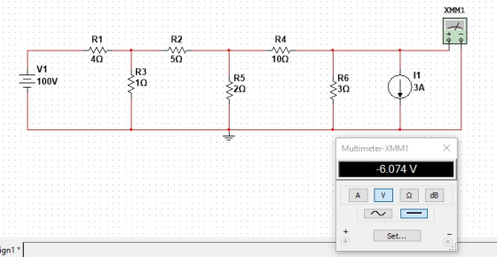
Terminal voltage is -6.074 V
8.
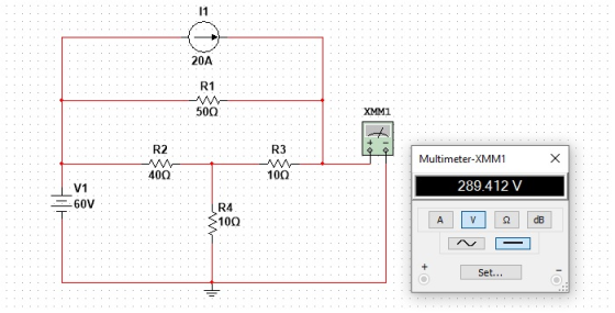
Terminal voltage is 289.412 V
9.
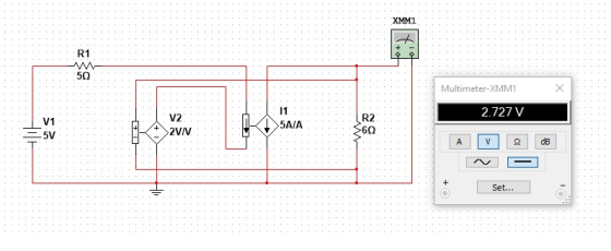
Terminal voltage is 2.727 V
Add Answer to:
Need help with Multisim to simulate these circuit diagrams. Any
Multisim works, preferrably Multisim Live
Problem...
Problem 7. Perform the following for the circuit below using the source transformation method 40 ...
 Need help with Multisim to simulate these circuit diagrams. Any
Multisim works, preferrably Multisim Live
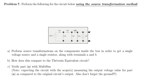
Problem 7. Perform the following for the circuit below using the source transformation method 40 5Ω 10Ω 100V 1Ω 20 30 3A a) Perform source transformations on the components inside the box in order to get a single voltage source and a single resistor, along with terminals a and b b) How does this compare to the Thévenin Equivalent circuit? c) Verify part (a) with...
Need help with Multisim to simulate these circuit diagrams. Any
Multisim works, preferrably Multisim Live
Problem 7. Perform the following for the circuit below using the source transformation method 40 5Ω 10Ω 100V 1Ω 20 30 3A a) Perform source transformations on the components inside the box in order to get a single voltage source and a single resistor, along with terminals a and b b) How does this compare to the Thévenin Equivalent circuit? c) Verify part (a) with...
Solve by hand and simulate in any electrical circuit simulator preferrably LTSpice Solve by hand only. Problem #4: Consider the circuit shown below. 6Ω /8 Ω 302 2700 V (rms) 40 2 Source-Line Load...
 Solve by hand and simulate in any electrical circuit
simulator preferrably LTSpice
Solve by hand only.
Problem #4: Consider the circuit shown below. 6Ω /8 Ω 302 2700 V (rms) 40 2 Source-Line Load (a) Find the real power dissipated in the line. (b) Find the capacitive reactance that when connected in parallel with the load will pl make the load look purely resistive. (c) What is the equivalent impedance of the load in (b)? (d) Find the real power...
Solve by hand and simulate in any electrical circuit
simulator preferrably LTSpice
Solve by hand only.
Problem #4: Consider the circuit shown below. 6Ω /8 Ω 302 2700 V (rms) 40 2 Source-Line Load (a) Find the real power dissipated in the line. (b) Find the capacitive reactance that when connected in parallel with the load will pl make the load look purely resistive. (c) What is the equivalent impedance of the load in (b)? (d) Find the real power...
EE 282-Circuit I Pre-Lab 9 Maximum Power Transfer Theorem Name Concepts: In this pre-lab we will ...
 EE 282-Circuit I Pre-Lab 9 Maximum Power Transfer Theorem Name Concepts: In this pre-lab we will be leaming about Maximum Power Transfer Theorem. Maximum power is transferred to the load when the load resistance equals the thexenin equivalent, and we carry out the analysis using Thevenin's equivalent circuit. In order to do this, first build the following circuit on Mutism. 1 R1 5.1k0 R3 2 V1 R2 8kQ 6.8㏀ Fig. 1 Part 1: To find the Thevenin equivalent resistance, we...
02 +Vo D3 Rgare 18 Circuit for Problem 1 Analysis 1. Copy the circuit of Figure 1.8 and sketch the ow of pesitive curment throughout the entire circuit for o>0. Repeat for n ce 2....
 02 +Vo D3 Rgare 18 Circuit for Problem 1 Analysis 1. Copy the circuit of Figure 1.8 and sketch the ow of pesitive curment throughout the entire circuit for o>0. Repeat for n ce 2. Plot two periods of nlt) and s) for each of the thee input wave shown in Figune 17 on page 37 fom output t (a) Feak value, and b) Eflective DC value, also known as RMS value NotTE These and are therefore optional 4. Determine...
PROBLEM: Simulate the resistance and the current across a circuit Consider the following circuit Where V-...
 PROBLEM: Simulate the resistance and the current across a circuit Consider the following circuit Where V- voltage from a battery source (unit of measure: Volts). I-Current (unit of measure: Amperes) And Ri, R. Rs are resistors connected in parallel (unit of measure: Ohms) When resistors are connected in parallel, the equivalent resistance, Ra, can be computed: By Ohm's Law, Components are designed to perform at a nominal value, however, due to manufacturing inconsistencies all components are subject to variation from...
can you sovle this problem, also I need the code for part d. thanks Problem #5 Ri Vy= Probe I R- 1502 o VOLTMETER IN...
 can you sovle this problem, also I need the code for part d.
thanks
Problem #5 Ri Vy= Probe I R- 1502 o VOLTMETER INPUT CIRCUIT Probe 2 Express resistance in ohms (2) and voltage in volts (V) Requirements-Part 1 (voltmeter not attached yet) a) Suppose you want to produce a voltage of 1 V across resistor R2 (i.e. Vor 1 V) Use the voltage divider equation to find the value of Ri that is needed to do this. b)...
can you sovle this problem, also I need the code for part d.
thanks
Problem #5 Ri Vy= Probe I R- 1502 o VOLTMETER INPUT CIRCUIT Probe 2 Express resistance in ohms (2) and voltage in volts (V) Requirements-Part 1 (voltmeter not attached yet) a) Suppose you want to produce a voltage of 1 V across resistor R2 (i.e. Vor 1 V) Use the voltage divider equation to find the value of Ri that is needed to do this. b)...
Problem 3: Design Problem On Figure P3a, you have a Common Source (CS) n-channel MOSFET amplifier....
 Problem 3: Design Problem On Figure P3a, you have a Common Source (CS) n-channel MOSFET amplifier. Notice the absence of a source resistor Rsig and load resistor R. If we know how the present amplifier (the one on Figure P3a) behaves without Rsig and RL, we can infer its behaviors if Rsig and R were to be added. design the amplifier circuit on Figure P3a, i.e., you have to find appropriate values for RGj You are to RG,, RD, and...
sedra smith book 7th edition chapter name is operational amplifier. question 12.1 to 12.10 I need...
 sedra smith book 7th edition chapter name is operational
amplifier. question 12.1 to 12.10 I need all solution with good
hand writing.
Problems 1075 Transistor Q3 WIL (um/um) 36/0.3 36/0.3 6/0.3 6/0.3 30/0.3 W/0.3 45/0.3 6/0.3 and A, if all devices are 0.3 m long, Q and Q2 are operated at overdrive voltages of 0.15-V magnitude, and Q is operated at Voy 0.2 V. Also, determine the op-amp output resistance 100 k2, C0.1 pF, G = 2 mA/V, R, =...
sedra smith book 7th edition chapter name is operational
amplifier. question 12.1 to 12.10 I need all solution with good
hand writing.
Problems 1075 Transistor Q3 WIL (um/um) 36/0.3 36/0.3 6/0.3 6/0.3 30/0.3 W/0.3 45/0.3 6/0.3 and A, if all devices are 0.3 m long, Q and Q2 are operated at overdrive voltages of 0.15-V magnitude, and Q is operated at Voy 0.2 V. Also, determine the op-amp output resistance 100 k2, C0.1 pF, G = 2 mA/V, R, =...
I only need help with the discussion there are many info that you do not need put I put just in ...
 I only need help with the discussion
there are many info that you do not need put I put just in
case as well as my data table.
please do it as soon as u can
Meauements ODeit1 Check2 Meaurements Checi3 Ced Check5 Check6 Measurements Check7 heck8 4058 33 536 1502 1035 979 119478 041 1.0319|0.554972| 64261| 153|15542033681 995781 5266566 1578807 298h 1631 119 1209430016 079096812 0.418135246 0,00032665 011890:004668155728441 0293237 1.291809502 1.22833 1.28 1952 -1116 4281 140616885511984206317 3346 8162 0.78...
I only need help with the discussion
there are many info that you do not need put I put just in
case as well as my data table.
please do it as soon as u can
Meauements ODeit1 Check2 Meaurements Checi3 Ced Check5 Check6 Measurements Check7 heck8 4058 33 536 1502 1035 979 119478 041 1.0319|0.554972| 64261| 153|15542033681 995781 5266566 1578807 298h 1631 119 1209430016 079096812 0.418135246 0,00032665 011890:004668155728441 0293237 1.291809502 1.22833 1.28 1952 -1116 4281 140616885511984206317 3346 8162 0.78...
1. Why can the DSO only measure node voltages when the Function Generator is the power supply in ...
 1. Why can the DSO only measure node voltages when the Function Generator is the power supply in a circuit (unless it is using a current probe)? 2. Consider Figure 1. According to the calculations in the lab handout, if Z-1kΩ +/6914, then the phase difference (фи-фі) between u(t) and i (t) is 34.6". a. If this v(t) and i(t) were displayed on a DSO (v(t) being a node voltage and using a current probe for i(t) as shown in...
 Need help with Multisim to simulate these circuit diagrams. Any
Multisim works, preferrably Multisim Live
Problem 7. Perform the following for the circuit below using the source transformation method 40 5Ω 10Ω 100V 1Ω 20 30 3A a) Perform source transformations on the components inside the box in order to get a single voltage source and a single resistor, along with terminals a and b b) How does this compare to the Thévenin Equivalent circuit? c) Verify part (a) with...
Need help with Multisim to simulate these circuit diagrams. Any
Multisim works, preferrably Multisim Live
Problem 7. Perform the following for the circuit below using the source transformation method 40 5Ω 10Ω 100V 1Ω 20 30 3A a) Perform source transformations on the components inside the box in order to get a single voltage source and a single resistor, along with terminals a and b b) How does this compare to the Thévenin Equivalent circuit? c) Verify part (a) with...
 Solve by hand and simulate in any electrical circuit
simulator preferrably LTSpice
Solve by hand only.
Problem #4: Consider the circuit shown below. 6Ω /8 Ω 302 2700 V (rms) 40 2 Source-Line Load (a) Find the real power dissipated in the line. (b) Find the capacitive reactance that when connected in parallel with the load will pl make the load look purely resistive. (c) What is the equivalent impedance of the load in (b)? (d) Find the real power...
Solve by hand and simulate in any electrical circuit
simulator preferrably LTSpice
Solve by hand only.
Problem #4: Consider the circuit shown below. 6Ω /8 Ω 302 2700 V (rms) 40 2 Source-Line Load (a) Find the real power dissipated in the line. (b) Find the capacitive reactance that when connected in parallel with the load will pl make the load look purely resistive. (c) What is the equivalent impedance of the load in (b)? (d) Find the real power...
 EE 282-Circuit I Pre-Lab 9 Maximum Power Transfer Theorem Name Concepts: In this pre-lab we will be leaming about Maximum Power Transfer Theorem. Maximum power is transferred to the load when the load resistance equals the thexenin equivalent, and we carry out the analysis using Thevenin's equivalent circuit. In order to do this, first build the following circuit on Mutism. 1 R1 5.1k0 R3 2 V1 R2 8kQ 6.8㏀ Fig. 1 Part 1: To find the Thevenin equivalent resistance, we...
 02 +Vo D3 Rgare 18 Circuit for Problem 1 Analysis 1. Copy the circuit of Figure 1.8 and sketch the ow of pesitive curment throughout the entire circuit for o>0. Repeat for n ce 2. Plot two periods of nlt) and s) for each of the thee input wave shown in Figune 17 on page 37 fom output t (a) Feak value, and b) Eflective DC value, also known as RMS value NotTE These and are therefore optional 4. Determine...
 PROBLEM: Simulate the resistance and the current across a circuit Consider the following circuit Where V- voltage from a battery source (unit of measure: Volts). I-Current (unit of measure: Amperes) And Ri, R. Rs are resistors connected in parallel (unit of measure: Ohms) When resistors are connected in parallel, the equivalent resistance, Ra, can be computed: By Ohm's Law, Components are designed to perform at a nominal value, however, due to manufacturing inconsistencies all components are subject to variation from...
 can you sovle this problem, also I need the code for part d.
thanks
Problem #5 Ri Vy= Probe I R- 1502 o VOLTMETER INPUT CIRCUIT Probe 2 Express resistance in ohms (2) and voltage in volts (V) Requirements-Part 1 (voltmeter not attached yet) a) Suppose you want to produce a voltage of 1 V across resistor R2 (i.e. Vor 1 V) Use the voltage divider equation to find the value of Ri that is needed to do this. b)...
can you sovle this problem, also I need the code for part d.
thanks
Problem #5 Ri Vy= Probe I R- 1502 o VOLTMETER INPUT CIRCUIT Probe 2 Express resistance in ohms (2) and voltage in volts (V) Requirements-Part 1 (voltmeter not attached yet) a) Suppose you want to produce a voltage of 1 V across resistor R2 (i.e. Vor 1 V) Use the voltage divider equation to find the value of Ri that is needed to do this. b)...
 Problem 3: Design Problem On Figure P3a, you have a Common Source (CS) n-channel MOSFET amplifier. Notice the absence of a source resistor Rsig and load resistor R. If we know how the present amplifier (the one on Figure P3a) behaves without Rsig and RL, we can infer its behaviors if Rsig and R were to be added. design the amplifier circuit on Figure P3a, i.e., you have to find appropriate values for RGj You are to RG,, RD, and...
 sedra smith book 7th edition chapter name is operational
amplifier. question 12.1 to 12.10 I need all solution with good
hand writing.
Problems 1075 Transistor Q3 WIL (um/um) 36/0.3 36/0.3 6/0.3 6/0.3 30/0.3 W/0.3 45/0.3 6/0.3 and A, if all devices are 0.3 m long, Q and Q2 are operated at overdrive voltages of 0.15-V magnitude, and Q is operated at Voy 0.2 V. Also, determine the op-amp output resistance 100 k2, C0.1 pF, G = 2 mA/V, R, =...
sedra smith book 7th edition chapter name is operational
amplifier. question 12.1 to 12.10 I need all solution with good
hand writing.
Problems 1075 Transistor Q3 WIL (um/um) 36/0.3 36/0.3 6/0.3 6/0.3 30/0.3 W/0.3 45/0.3 6/0.3 and A, if all devices are 0.3 m long, Q and Q2 are operated at overdrive voltages of 0.15-V magnitude, and Q is operated at Voy 0.2 V. Also, determine the op-amp output resistance 100 k2, C0.1 pF, G = 2 mA/V, R, =...
 I only need help with the discussion
there are many info that you do not need put I put just in
case as well as my data table.
please do it as soon as u can
Meauements ODeit1 Check2 Meaurements Checi3 Ced Check5 Check6 Measurements Check7 heck8 4058 33 536 1502 1035 979 119478 041 1.0319|0.554972| 64261| 153|15542033681 995781 5266566 1578807 298h 1631 119 1209430016 079096812 0.418135246 0,00032665 011890:004668155728441 0293237 1.291809502 1.22833 1.28 1952 -1116 4281 140616885511984206317 3346 8162 0.78...
I only need help with the discussion
there are many info that you do not need put I put just in
case as well as my data table.
please do it as soon as u can
Meauements ODeit1 Check2 Meaurements Checi3 Ced Check5 Check6 Measurements Check7 heck8 4058 33 536 1502 1035 979 119478 041 1.0319|0.554972| 64261| 153|15542033681 995781 5266566 1578807 298h 1631 119 1209430016 079096812 0.418135246 0,00032665 011890:004668155728441 0293237 1.291809502 1.22833 1.28 1952 -1116 4281 140616885511984206317 3346 8162 0.78...
 1. Why can the DSO only measure node voltages when the Function Generator is the power supply in a circuit (unless it is using a current probe)? 2. Consider Figure 1. According to the calculations in the lab handout, if Z-1kΩ +/6914, then the phase difference (фи-фі) between u(t) and i (t) is 34.6". a. If this v(t) and i(t) were displayed on a DSO (v(t) being a node voltage and using a current probe for i(t) as shown in...
Most questions answered within 3 hours.
-
2) You are given the task of finding a representation for a
circle in a drawing...
asked 1 hour ago -
STUDY QUESTION: Does use of diet drug fen-phen
(fenfluramine-phentermine) cause valvular heart disease?
HINT: Valvular heart...
asked 51 minutes ago -
1. An object weighing 40 N rests on a surface. The coefficient
of friction is 0.35....
asked 2 hours ago -
Investor company owns 35% of investee company voting stock and
accounts for the investment under the...
asked 3 hours ago -
The number of major faults on a randomly chosen 1 km stretch of
highway has a...
asked 3 hours ago -
Consider the competitive environment of Starbuck's, Progressive
Insurance, a manufacturing firm with low turnover, or a...
asked 4 hours ago -
3. Gains from trade
Consider two neighbouring island countries called Euphoria and
Contente. They each have...
asked 6 hours ago -
A business executive has the option to invest money in two
plans: Plan A guarantees that...
asked 8 hours ago -
Hello, can someone please help me answer this question?
How much heat is absorbed by a...
asked 8 hours ago -
. A marketing researcher conducted a survey of 25 shoppers
randomly selected at the local mall...
asked 8 hours ago -
Create an comprehensive response to the
following:
Antimicrobial agents work on a multitude of microbes (bacteria,...
asked 8 hours ago -
6.13 LAB: Step counter. Section 6.3.
A pedometer treats walking 2,000 steps as walking 1 mile....
asked 8 hours ago