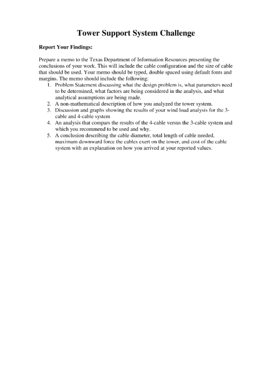
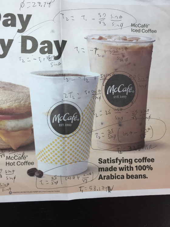
please help! I need help finding and solving equations of equilibrium to find the max tension in the cables and the angle that results in the maximum tension, I also have pictures below of the work I have so far all I really need is equations for the 4 cable part and that's it but I put the whole assignment so you could see thanks!
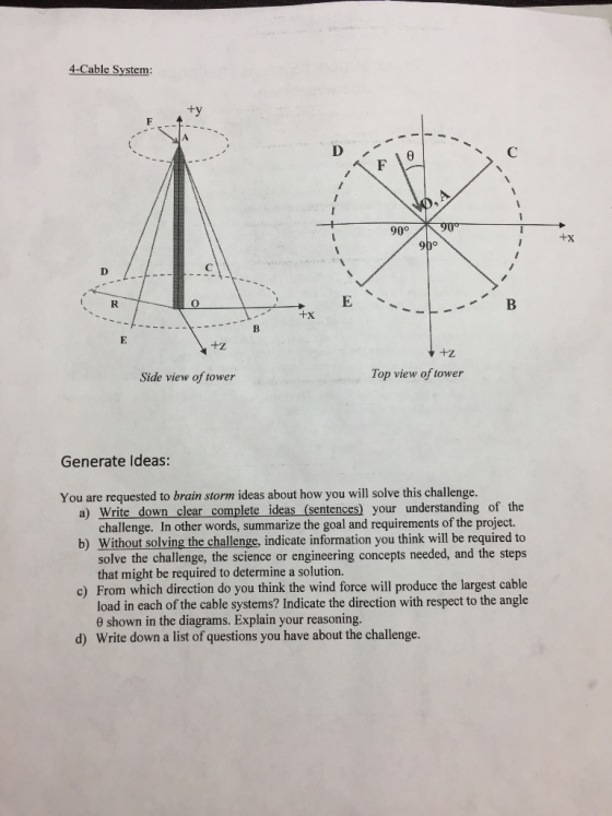


4-Cable System ty 90° I+x +Z +Z Side view of tower Top view of tower Generate Ideas: You are requested to brain storm ideas about how you will solve this challenge. a) Write down clear complete ideas (sentences) your understanding of the challenge. In other words, summarize the goal and requirements of the project. b) Without solving the challenge, indicate information you think will be required to solve the challenge, the science or engineering concepts needed, and the steps that might be required to determine a solution. c) From which direction do you think the wind force will produce the largest cable load in each of the cable systems? Indicate the direction with respect to the angle 0 shown in the diagrams. Explain your reasoning. d) Write down a list of questions you have about the challenge.
Tower Support System Challenge System Gcomctry: Before a force analysis can be conducted on the system, you need to work out the geometry of the system using the provided coordinate system. You will do so as follows: 1. Locate the coordinates, (x.y.z), of the cables anchor points using the information ovided on the tower diagrams 3 Cable System Anchor Point Coordinates x.ν.z 4 Cable System Anchor Point Coordinates 2. Use the coordinate of the system to define the position vectors that point from the top of the tower to each anchor point, Use the position vectors to determine the unit vectors that define the orientation of each cable in space pointing Irom the top of the tower to each anchor point. 3. Position and Unit vectors for the 3 Cable System: Cable AB; Cable AC Cable AD Position and Unit vectors for the 4 cable system: Cable AB: Cable AC: Cable AD: Cable AE:
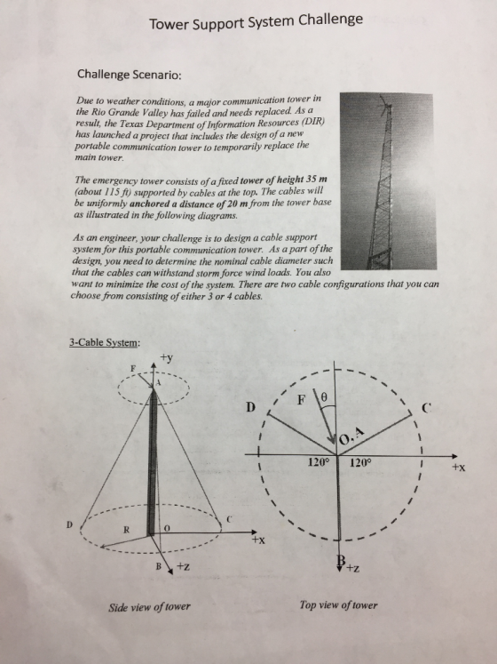
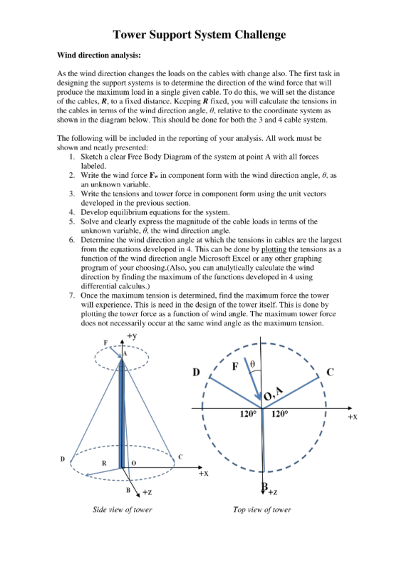
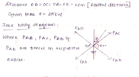
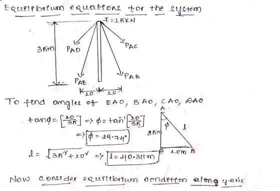
Tower Support System Challenge Wind direction analysis: As the wind direction changes the loads on the cables with change also. The first task in designing the support systems is to determine the direction of the wind force that will produce the maximum load in a single given cable. To do this, we will set the distance of the cables, R, to a fixed distance. Keeping R fixed, you will calculate the tensions in the cables in terms of the wind direction angle, 0, relative to the coordinate system as shown in the diagram below. This should be done for both the 3 and 4 cable system The following will be included in the reporting of your analysis. All work must be shown and neatly presented 1. Sketch a clear Free Body Diagram of the system at point A with all forces labeled an unknown variable developed in the previous section 2, write the wind force Fw in component form with the wind direction angle, θ, as 3. Write the tensions and tower force in component form using the unit vectors 4. Develop equilibrium equations for the system. 5. Solve and clearly express the magnitude of the cable loads in terms of the unknown variable, 9, the wind direction angle. 6. Determine the wind direction angle at which the tensions in cables are the largest from the equations developed in 4. This can be done by plotting the tensions as a function of the wind direction angle Microsoft Excel or any other graphing program of your choosing.(Also, you can analytically calculate the wind direction by finding the maximum of the functions developed in 4 using differential calculus.) 7. Once the maximum tension is determined, find the maximum force the tower will experience. This is need in the design of the tower itself. This is done by plotting the tower force as a function of wind angle. The maximum tower force does not necessarily occur at the same wind angle as the maximum tension 120 120 +X 0 +Z Side view of tower Top view of tower
ay cCafé Iced Coffee Da 闷 2 McCafe 2. EST. 1993 McCafe EST. 1993 25 McCafé Hot Coffee Satisfying coffee made with 100% t-ces sel Arabica beans. CaS VR $ PRİNTEO ON RECYCLED PAPER S0% Post-Consumer Content
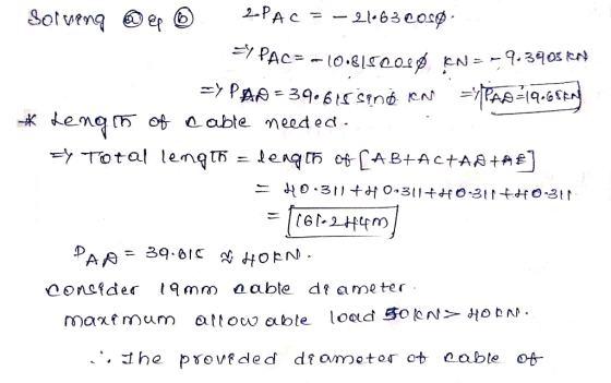
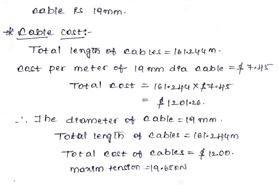
Analysis Based on the calculations, the (Blank) Cable system is the safest and most cost-effective design that can be used. The maximum tension recorded was approximately (Blank Tension)kN as opposed to (Blank Tension)kN. The tension was measured while the wind angle for Ta was 30-degree meanwhile T was at 0 degrees. TABLE TITLE: SystemMax. Tension Wind angle Max. Tower Cable size Total cable Total cable kN 58.1 Force (kN) (mm) length (m 120.93 cost (USD) 3-cable 4-cable 30 1189.95 Conclusions Based on your analysis in the previous section, clearly state which cabling system you recommend and why. Make sure to state how cable size, cost, maximum tensions, and the tower force were used to make your decision.
Homework Answers


Add Answer to:
Please help! I need help finding and solving equations of equilibrium to find the max tension in ...
Please do show every bit of work out Thanks Question 1 Figure 1 Figure 1 represents...
 Please do show every bit of work out
Thanks
Question 1 Figure 1 Figure 1 represents a bulldozer exerting a force of F- 2i kN at point A. If the tension a The positions of point C with respect to point D, and of point B with respect to in cable AB is 780.31 N, calculate: point C b The distances between point B and point D and between point C and point A c The unit vectors that determine...
Please do show every bit of work out
Thanks
Question 1 Figure 1 Figure 1 represents a bulldozer exerting a force of F- 2i kN at point A. If the tension a The positions of point C with respect to point D, and of point B with respect to in cable AB is 780.31 N, calculate: point C b The distances between point B and point D and between point C and point A c The unit vectors that determine...
Homework 6 Cable Subjected to Concentrated Loads Car der the cable nくFgure 1). The given dimensions...
 Homework 6 Cable Subjected to Concentrated Loads Car der the cable nくFgure 1). The given dimensions are Δ띠-6 m . Δ:r,-6 m ΔΖ3-8 n. and Δ3,-a tn Cable BCis horizontal. The applied loads are B1-4 kN and C '- 5 kN. The designer aid li ta knaw where the brackrt for print D must be placed and what the tension will ba in all threr segments Review Learning Goal: Part A Deeine how to sove the problern To sove for...
Three-Dimensional Force Systems cable AC Part A Finding the tension Learning Goal: weight of 115 lb...
 Three-Dimensional Force Systems cable AC Part A Finding the tension Learning Goal: weight of 115 lb acts at C on the strut. Find the magnitude of the tension in cable AC To apply the condition of equilibrium to three-dimensional systems and solve for unknown forces. Express your answer to three significant figures and include the appropriate units. View Available Hint(s) As shown, a mass is being lifted by a strut that is supported by two cables AC and CD. The...
Part A-Finding the tension in cable AC A weight of 175 lb acts at C on...
 Part A-Finding the tension in cable AC A weight of 175 lb acts at C on the strut. Find the magnitude of the tension in cable AC. Learning Goal: Express your answer to three significant figures and include the appropriate units. To apply the condition of equilibrium to three- dimensional systems and solve for unknown forces. View Available Hint(s) As shown, a mass is being lifted by a strut that is supported by two cables AC and CD. The dimensions...
Question 2 (15 points): Tension, Compression and Zero-Force Members in a Truss Structure. Consider the truss...
 Question 2 (15 points): Tension, Compression and Zero-Force Members in a Truss Structure. Consider the truss structure shown in Figure 2. 3P (kN) P (kN) I LI LL Figure 2: Elevation view of 27 bar truss structure. Vertical loads of 3P kN and P kN are applied at nodes B and D, respectively. [2a) (3 pts). Compute the magnitude and direction of the total support reactions at points A and C. [25] (3 pts). Identify the zero-force members (If you...
The inclined pole is subjected to a 5 kN magnitude force vector F acting from point...
 The inclined pole is subjected to a 5 kN magnitude force vector F acting from point B towards point C. (a) Determine the angle that exists between B (1,5,6) m the force vector F and the pole AB (b) Determine the magnitude of the component of the force vector F that acts parallel to the pole AB (c) Determine the magnitude of the component of the force vector that acts perpendicular to the pole AbB C (4, 3, 0) m...
Need help with E and F please. 3. The beam shown in the figure below is...
 Need help with E and F please.
3. The beam shown in the figure below is carrying superimposed dead load of 25 kN/m and use and occupancy load of 45 kN/m. For preliminary analysis, assume a self weight of 10 kN/m. We are required to find the maximum positive (tension at the bottom) and negative (tension at the top) moments due to the factored loads, and then design the beam CIV E 374-RC-Lab 3 Fall 2018 (a) Determine the maximum...
Need help with E and F please.
3. The beam shown in the figure below is carrying superimposed dead load of 25 kN/m and use and occupancy load of 45 kN/m. For preliminary analysis, assume a self weight of 10 kN/m. We are required to find the maximum positive (tension at the bottom) and negative (tension at the top) moments due to the factored loads, and then design the beam CIV E 374-RC-Lab 3 Fall 2018 (a) Determine the maximum...
Please help me with both parts b and c. I am confused Constants A 9.00 m...
 Please help me with both parts
b and c. I am confused
Constants A 9.00 m uniform beam is hinged to a vertical wall and held horizontally by a 5.00 m cable attached to the wall 4.00 m above the hinge, as shown in the figure below (Figure 1). The metal of this cable has a test strength of 1.10 kN , which means that it will break if the tension in it exceeds that amount. Part A What is...
Please help me with both parts
b and c. I am confused
Constants A 9.00 m uniform beam is hinged to a vertical wall and held horizontally by a 5.00 m cable attached to the wall 4.00 m above the hinge, as shown in the figure below (Figure 1). The metal of this cable has a test strength of 1.10 kN , which means that it will break if the tension in it exceeds that amount. Part A What is...
please help both parts thx so much for help Question 3 1) Consider Beam ACB in...
 please help both parts thx so much for help
Question 3 1) Consider Beam ACB in Figure Q3(1), determine the maximum positive moment at point C (mid-point of span AB) of the beam and show the corresponding locations of the moving loads. A moment rendering the beam bottom tension is considered positive. (14 marks) 8 kN 4 kN 6 kN 5 m Figure Q3(1) 2) Consider the cantilever shown in Figure Q3(2), draw the influence lines for (a) the moment...
please help both parts thx so much for help
Question 3 1) Consider Beam ACB in Figure Q3(1), determine the maximum positive moment at point C (mid-point of span AB) of the beam and show the corresponding locations of the moving loads. A moment rendering the beam bottom tension is considered positive. (14 marks) 8 kN 4 kN 6 kN 5 m Figure Q3(1) 2) Consider the cantilever shown in Figure Q3(2), draw the influence lines for (a) the moment...
I would like a step by step solution please and clear to read. Surface Tension and...
 I would like a step by step solution please and clear to
read.
Surface Tension and Bubbles Surface tension is a force caused by the attraction of liquid molecules on a boundary surface for each other. It acts tangential to the surface and is modeled as a single number, the surface tension Consider a square film on a wire frame. The bottom edge is movable and, when the frame is vertical, as shown, the surface tension of the film pulls...
I would like a step by step solution please and clear to
read.
Surface Tension and Bubbles Surface tension is a force caused by the attraction of liquid molecules on a boundary surface for each other. It acts tangential to the surface and is modeled as a single number, the surface tension Consider a square film on a wire frame. The bottom edge is movable and, when the frame is vertical, as shown, the surface tension of the film pulls...
 Please do show every bit of work out
Thanks
Question 1 Figure 1 Figure 1 represents a bulldozer exerting a force of F- 2i kN at point A. If the tension a The positions of point C with respect to point D, and of point B with respect to in cable AB is 780.31 N, calculate: point C b The distances between point B and point D and between point C and point A c The unit vectors that determine...
Please do show every bit of work out
Thanks
Question 1 Figure 1 Figure 1 represents a bulldozer exerting a force of F- 2i kN at point A. If the tension a The positions of point C with respect to point D, and of point B with respect to in cable AB is 780.31 N, calculate: point C b The distances between point B and point D and between point C and point A c The unit vectors that determine...
 Homework 6 Cable Subjected to Concentrated Loads Car der the cable nくFgure 1). The given dimensions are Δ띠-6 m . Δ:r,-6 m ΔΖ3-8 n. and Δ3,-a tn Cable BCis horizontal. The applied loads are B1-4 kN and C '- 5 kN. The designer aid li ta knaw where the brackrt for print D must be placed and what the tension will ba in all threr segments Review Learning Goal: Part A Deeine how to sove the problern To sove for...
 Three-Dimensional Force Systems cable AC Part A Finding the tension Learning Goal: weight of 115 lb acts at C on the strut. Find the magnitude of the tension in cable AC To apply the condition of equilibrium to three-dimensional systems and solve for unknown forces. Express your answer to three significant figures and include the appropriate units. View Available Hint(s) As shown, a mass is being lifted by a strut that is supported by two cables AC and CD. The...
 Part A-Finding the tension in cable AC A weight of 175 lb acts at C on the strut. Find the magnitude of the tension in cable AC. Learning Goal: Express your answer to three significant figures and include the appropriate units. To apply the condition of equilibrium to three- dimensional systems and solve for unknown forces. View Available Hint(s) As shown, a mass is being lifted by a strut that is supported by two cables AC and CD. The dimensions...
 Question 2 (15 points): Tension, Compression and Zero-Force Members in a Truss Structure. Consider the truss structure shown in Figure 2. 3P (kN) P (kN) I LI LL Figure 2: Elevation view of 27 bar truss structure. Vertical loads of 3P kN and P kN are applied at nodes B and D, respectively. [2a) (3 pts). Compute the magnitude and direction of the total support reactions at points A and C. [25] (3 pts). Identify the zero-force members (If you...
 The inclined pole is subjected to a 5 kN magnitude force vector F acting from point B towards point C. (a) Determine the angle that exists between B (1,5,6) m the force vector F and the pole AB (b) Determine the magnitude of the component of the force vector F that acts parallel to the pole AB (c) Determine the magnitude of the component of the force vector that acts perpendicular to the pole AbB C (4, 3, 0) m...
 Need help with E and F please.
3. The beam shown in the figure below is carrying superimposed dead load of 25 kN/m and use and occupancy load of 45 kN/m. For preliminary analysis, assume a self weight of 10 kN/m. We are required to find the maximum positive (tension at the bottom) and negative (tension at the top) moments due to the factored loads, and then design the beam CIV E 374-RC-Lab 3 Fall 2018 (a) Determine the maximum...
Need help with E and F please.
3. The beam shown in the figure below is carrying superimposed dead load of 25 kN/m and use and occupancy load of 45 kN/m. For preliminary analysis, assume a self weight of 10 kN/m. We are required to find the maximum positive (tension at the bottom) and negative (tension at the top) moments due to the factored loads, and then design the beam CIV E 374-RC-Lab 3 Fall 2018 (a) Determine the maximum...
 Please help me with both parts
b and c. I am confused
Constants A 9.00 m uniform beam is hinged to a vertical wall and held horizontally by a 5.00 m cable attached to the wall 4.00 m above the hinge, as shown in the figure below (Figure 1). The metal of this cable has a test strength of 1.10 kN , which means that it will break if the tension in it exceeds that amount. Part A What is...
Please help me with both parts
b and c. I am confused
Constants A 9.00 m uniform beam is hinged to a vertical wall and held horizontally by a 5.00 m cable attached to the wall 4.00 m above the hinge, as shown in the figure below (Figure 1). The metal of this cable has a test strength of 1.10 kN , which means that it will break if the tension in it exceeds that amount. Part A What is...
 please help both parts thx so much for help
Question 3 1) Consider Beam ACB in Figure Q3(1), determine the maximum positive moment at point C (mid-point of span AB) of the beam and show the corresponding locations of the moving loads. A moment rendering the beam bottom tension is considered positive. (14 marks) 8 kN 4 kN 6 kN 5 m Figure Q3(1) 2) Consider the cantilever shown in Figure Q3(2), draw the influence lines for (a) the moment...
please help both parts thx so much for help
Question 3 1) Consider Beam ACB in Figure Q3(1), determine the maximum positive moment at point C (mid-point of span AB) of the beam and show the corresponding locations of the moving loads. A moment rendering the beam bottom tension is considered positive. (14 marks) 8 kN 4 kN 6 kN 5 m Figure Q3(1) 2) Consider the cantilever shown in Figure Q3(2), draw the influence lines for (a) the moment...
 I would like a step by step solution please and clear to
read.
Surface Tension and Bubbles Surface tension is a force caused by the attraction of liquid molecules on a boundary surface for each other. It acts tangential to the surface and is modeled as a single number, the surface tension Consider a square film on a wire frame. The bottom edge is movable and, when the frame is vertical, as shown, the surface tension of the film pulls...
I would like a step by step solution please and clear to
read.
Surface Tension and Bubbles Surface tension is a force caused by the attraction of liquid molecules on a boundary surface for each other. It acts tangential to the surface and is modeled as a single number, the surface tension Consider a square film on a wire frame. The bottom edge is movable and, when the frame is vertical, as shown, the surface tension of the film pulls...
Most questions answered within 3 hours.
-
what statement accurately depicts the similarities in
requirements between payroll and human resources function
asked 1 hour ago -
Calculate the volume integral of the function T=z^2 over the
tetrahedron with corners (0,0,0), (1,0,0), (0,1,0),...
asked 3 hours ago -
I propose to you a game. You roll 2 dice. If the sum of the
numbers...
asked 4 hours ago -
Select the most likely lattice types for each of the following
salts: (a) BeF2; (b) CaO;...
asked 4 hours ago -
a
ball is thrown downward with velocity of 10m/s. calculate the final
velocity if it reaches...
asked 5 hours ago -
How many grams of ice at -15°C must be added to 705 grams of
water that...
asked 6 hours ago -
2. Balance sheet
The balance sheet provides a snapshot of the financial condition
of a company....
asked 6 hours ago -
In week 1 of the chemical equilibrium experiment, you and your
lab team will create a...
asked 7 hours ago -
Identify and describe five (5) characteristics of a good KM
measurement system. Be sure to include...
asked 7 hours ago -
What are at least five (5) workplace wellness best practices for
a successful wellness program? Explain...
asked 7 hours ago -
A pharmaceutical company is testing a new drug. Of the 110
people that received the drug,...
asked 7 hours ago -
Which of the following is NOT a mechanism for gene
regulation?
a. Phase variation in DNA....
asked 7 hours ago