![nsS Student ID First part-Theeretical [5 points, 15 minutes: Answer the follewing questions: II point] For a sinusoidal signa](http://img.homeworklib.com/images/d119266a-ff0d-4f36-b9c1-44a4cfe0ebb7.png?x-oss-process=image/resize,w_560)
Homework Answers
Add Answer to:
NsS Student ID First part-Theeretical [5 points, 15 minutes: Answer the follewing questions: II p...
Draw the correct waveforms in the aranhs below for questions 10: 8. With the oscilloscope AC...
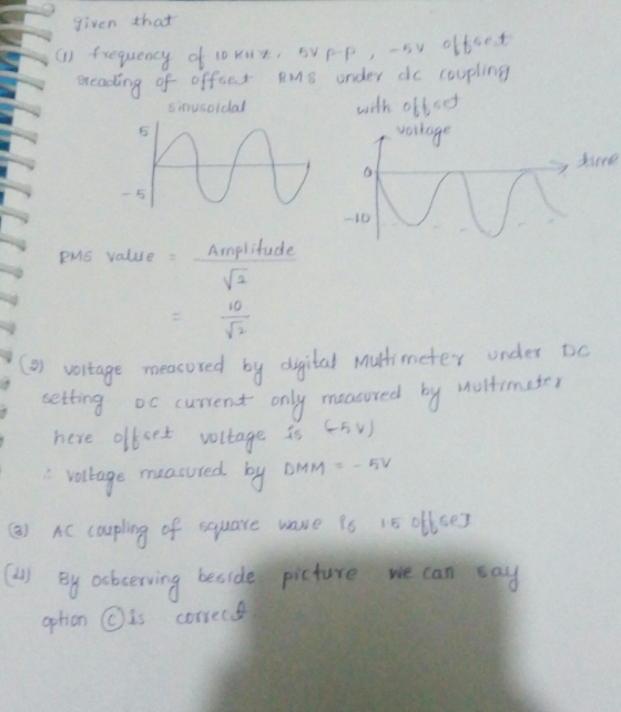
 Draw the correct waveforms in the aranhs below for questions 10: 8. With the oscilloscope AC coupled, draw the signal display you would expect to see on the screen of the oscilloscope on the graph provided below. SWITCH SETTINGS TIME/DIV 50 us VOLTS/DIV → 2 V SIGNAL PARAMETERS TH 12 Vdc 9. With the oscilloscope DC coupled, draw the signal display you would expect to see on the screen of the oscilloscope on the graph provided below. SWITCH SETTINGS TIME/DIV...
Please answer questions 4 and 5 if you can, thank you in advance!! 1. Build the...
 Please answer questions 4 and 5 if you can, thank you in
advance!!
1. Build the circuit shown below V. 2 V. 5900-RC 1 k2 1Vin t Vin(t) Function Generator 5900-RC 2. Set the Function Generator such that Vin(t) is a 3 V peak-peak sinusoidal signal at a frequency of 1 kHz. You can do this by varying the amplitude of the function generator when the generator is connected directly into the "input" of the oscilloscope. To test your ability...
Please answer questions 4 and 5 if you can, thank you in
advance!!
1. Build the circuit shown below V. 2 V. 5900-RC 1 k2 1Vin t Vin(t) Function Generator 5900-RC 2. Set the Function Generator such that Vin(t) is a 3 V peak-peak sinusoidal signal at a frequency of 1 kHz. You can do this by varying the amplitude of the function generator when the generator is connected directly into the "input" of the oscilloscope. To test your ability...
*USE Multisim( Provide Pictures of work on Multisim for each step) and Fill the Tables Below...
 *USE Multisim( Provide Pictures of work on Multisim for each
step) and Fill the Tables Below
PROCEDURE: Review the front panel controls in each of the major groups. Then turn on the oscilloscope, select Chl, set the SEC/DIV to 0.1 ms/div, select AUTO triggering, and obtain a line across the face of the CRT. Although many of the measurements described in this experiment are automated in newer scopes, it is useful to learn to make these measurements manually. Turn on...
*USE Multisim( Provide Pictures of work on Multisim for each
step) and Fill the Tables Below
PROCEDURE: Review the front panel controls in each of the major groups. Then turn on the oscilloscope, select Chl, set the SEC/DIV to 0.1 ms/div, select AUTO triggering, and obtain a line across the face of the CRT. Although many of the measurements described in this experiment are automated in newer scopes, it is useful to learn to make these measurements manually. Turn on...
I need quick help this question please less than 30 minutes the answer tonains b pages, 3 questions and the duration is...
 I need quick help this question please less than 30 minutes the
answer
tonains b pages, 3 questions and the duration is 120 minutes. 2s A4 cheat-sheets and calculators are allowed QUESTIONS he following current controlled signal attenuator circuit.เ is a DC current source that controls the attenuation factor. R.-4kf2 and k-4 mAN v™-osv ter the diode connected MSRT device.V" is a sinusoidal input signal. Coupling capacitors C-c, are very large they bibck lhe DC current and pass the AC...
I need quick help this question please less than 30 minutes the
answer
tonains b pages, 3 questions and the duration is 120 minutes. 2s A4 cheat-sheets and calculators are allowed QUESTIONS he following current controlled signal attenuator circuit.เ is a DC current source that controls the attenuation factor. R.-4kf2 and k-4 mAN v™-osv ter the diode connected MSRT device.V" is a sinusoidal input signal. Coupling capacitors C-c, are very large they bibck lhe DC current and pass the AC...
please the answer it doesn't really matter, I really need a good explanation of how to clearly understand this pleas...
 please the answer it doesn't really matter, I really need a good
explanation of how to clearly understand this please show your
working if you can
also please with a readable handwriting
23. WAVES a. Explain the difference between transverse and longitudinal waves. f(t)-A sin(wt + φ) Consider the following sine wave: b. Explain the name and function of A, a, and ф. Give units of measure, if relevant. c. What is the value of w for a 50Hz sinusoidal...
please the answer it doesn't really matter, I really need a good
explanation of how to clearly understand this please show your
working if you can
also please with a readable handwriting
23. WAVES a. Explain the difference between transverse and longitudinal waves. f(t)-A sin(wt + φ) Consider the following sine wave: b. Explain the name and function of A, a, and ф. Give units of measure, if relevant. c. What is the value of w for a 50Hz sinusoidal...
checking to see if the answers i got are correct and help with the other parts....
 checking to see if the answers i got are correct and help with
the other parts. thank you
Chapter 26 Laboratory Application Assignment In this lab application assignment you will examine an RC coupling circuit and an RC low-pass filter. In the RC coulina circuit you will see how the series capacitor blocks the de component of the input voltage but passes the ac component. In the RC low-pass filter you will see how the low frequencies are passed from...
checking to see if the answers i got are correct and help with
the other parts. thank you
Chapter 26 Laboratory Application Assignment In this lab application assignment you will examine an RC coupling circuit and an RC low-pass filter. In the RC coulina circuit you will see how the series capacitor blocks the de component of the input voltage but passes the ac component. In the RC low-pass filter you will see how the low frequencies are passed from...
5,6,7 5- Theoretical Part: For the same above circuit (Part B), First, change Rx to 2.2K....
 5,6,7
5- Theoretical Part: For the same above circuit (Part B), First, change Rx to 2.2K. What is the maximum peak input voltage before Vout just saturates? Assume the dc input is still at 1.5V (unchanged) (Assume Vsat = 10Volts ) Vin(pk) maximum = ......................-Volts 6- Verify the theoretical result in 5 by slowly varying the amplitude of the input signal until Vout just saturates (about to saturate). What is the corresponding Vin(pk)? Vin(pk) maximum = ................. Volts 7. If...
5,6,7
5- Theoretical Part: For the same above circuit (Part B), First, change Rx to 2.2K. What is the maximum peak input voltage before Vout just saturates? Assume the dc input is still at 1.5V (unchanged) (Assume Vsat = 10Volts ) Vin(pk) maximum = ......................-Volts 6- Verify the theoretical result in 5 by slowly varying the amplitude of the input signal until Vout just saturates (about to saturate). What is the corresponding Vin(pk)? Vin(pk) maximum = ................. Volts 7. If...
DC-AC inverters have many commercial and residential applications, including uninterruptible powe...
 DC-AC inverters have many commercial and residential applications, including uninterruptible power supply (UPS) units, adjustable speed drives (ASD) for AC motors, and electronic frequency changer circuits. They are also used in solar electrical systems where batteries are charged from solar panels and used as the input DC voltage source. The inverter circuit converts the DC into AC voltage of desired frequency. Most of us are also familiar with HVDC transmission systems, where high voltages are first converted from AC to...
I am really need these solutions. Can your help me please? this is a last part...
 I am really need these solutions. Can your help me please?
this is a last part for my class final. I am really stuck at
it
Problem 1 If v(t) = 80 cos(200t) V and i(t) = 180 cos(200t + 75°) mA for some load, then calculate the instantaneous power and average power absorbed by the load Problem 2 Find the average power absorbed by the 102 resistor in the circuit below 492 -15.2 20/45°v 01v. 81. 59 109 {v....
I am really need these solutions. Can your help me please?
this is a last part for my class final. I am really stuck at
it
Problem 1 If v(t) = 80 cos(200t) V and i(t) = 180 cos(200t + 75°) mA for some load, then calculate the instantaneous power and average power absorbed by the load Problem 2 Find the average power absorbed by the 102 resistor in the circuit below 492 -15.2 20/45°v 01v. 81. 59 109 {v....
hy I need answers of these questions according to data sheet. thank you DATA SHEET PARTI...
 hy I need answers of these questions according to data
sheet. thank you
DATA SHEET PARTI TIME/DIV ims VOLTS/DIV=_IV PEAK VOLTAGE V_47 toms TIME/DIV=_ms VOLTS/DIV-5V PEAK VOLTAGE V_42 PERIOD TO_loms PERIOD T- PART 1 SINEWAVE Vrms (VOLTS) VP (VOLTS) (Voltmeter) (oscilloscope) 7:07 10 3.57 5 2: 78 4 2.10 3 2 Slope=0.707V TIME/DIV=_ams VOLTS/DIVE PEAK VOLTAGE V=_41_ PERIOD T=_toms PART III SQUAREWAVE VAMS (VOLTS) VP (VOLTS) (Voltmeter) (oscilloscope) 10.9 do 542 S 4.4 4 3:3 고 2-2 Slope 0-92-1v PART...
hy I need answers of these questions according to data
sheet. thank you
DATA SHEET PARTI TIME/DIV ims VOLTS/DIV=_IV PEAK VOLTAGE V_47 toms TIME/DIV=_ms VOLTS/DIV-5V PEAK VOLTAGE V_42 PERIOD TO_loms PERIOD T- PART 1 SINEWAVE Vrms (VOLTS) VP (VOLTS) (Voltmeter) (oscilloscope) 7:07 10 3.57 5 2: 78 4 2.10 3 2 Slope=0.707V TIME/DIV=_ams VOLTS/DIVE PEAK VOLTAGE V=_41_ PERIOD T=_toms PART III SQUAREWAVE VAMS (VOLTS) VP (VOLTS) (Voltmeter) (oscilloscope) 10.9 do 542 S 4.4 4 3:3 고 2-2 Slope 0-92-1v PART...
 Draw the correct waveforms in the aranhs below for questions 10: 8. With the oscilloscope AC coupled, draw the signal display you would expect to see on the screen of the oscilloscope on the graph provided below. SWITCH SETTINGS TIME/DIV 50 us VOLTS/DIV → 2 V SIGNAL PARAMETERS TH 12 Vdc 9. With the oscilloscope DC coupled, draw the signal display you would expect to see on the screen of the oscilloscope on the graph provided below. SWITCH SETTINGS TIME/DIV...
 Please answer questions 4 and 5 if you can, thank you in
advance!!
1. Build the circuit shown below V. 2 V. 5900-RC 1 k2 1Vin t Vin(t) Function Generator 5900-RC 2. Set the Function Generator such that Vin(t) is a 3 V peak-peak sinusoidal signal at a frequency of 1 kHz. You can do this by varying the amplitude of the function generator when the generator is connected directly into the "input" of the oscilloscope. To test your ability...
Please answer questions 4 and 5 if you can, thank you in
advance!!
1. Build the circuit shown below V. 2 V. 5900-RC 1 k2 1Vin t Vin(t) Function Generator 5900-RC 2. Set the Function Generator such that Vin(t) is a 3 V peak-peak sinusoidal signal at a frequency of 1 kHz. You can do this by varying the amplitude of the function generator when the generator is connected directly into the "input" of the oscilloscope. To test your ability...
 *USE Multisim( Provide Pictures of work on Multisim for each
step) and Fill the Tables Below
PROCEDURE: Review the front panel controls in each of the major groups. Then turn on the oscilloscope, select Chl, set the SEC/DIV to 0.1 ms/div, select AUTO triggering, and obtain a line across the face of the CRT. Although many of the measurements described in this experiment are automated in newer scopes, it is useful to learn to make these measurements manually. Turn on...
*USE Multisim( Provide Pictures of work on Multisim for each
step) and Fill the Tables Below
PROCEDURE: Review the front panel controls in each of the major groups. Then turn on the oscilloscope, select Chl, set the SEC/DIV to 0.1 ms/div, select AUTO triggering, and obtain a line across the face of the CRT. Although many of the measurements described in this experiment are automated in newer scopes, it is useful to learn to make these measurements manually. Turn on...
 I need quick help this question please less than 30 minutes the
answer
tonains b pages, 3 questions and the duration is 120 minutes. 2s A4 cheat-sheets and calculators are allowed QUESTIONS he following current controlled signal attenuator circuit.เ is a DC current source that controls the attenuation factor. R.-4kf2 and k-4 mAN v™-osv ter the diode connected MSRT device.V" is a sinusoidal input signal. Coupling capacitors C-c, are very large they bibck lhe DC current and pass the AC...
I need quick help this question please less than 30 minutes the
answer
tonains b pages, 3 questions and the duration is 120 minutes. 2s A4 cheat-sheets and calculators are allowed QUESTIONS he following current controlled signal attenuator circuit.เ is a DC current source that controls the attenuation factor. R.-4kf2 and k-4 mAN v™-osv ter the diode connected MSRT device.V" is a sinusoidal input signal. Coupling capacitors C-c, are very large they bibck lhe DC current and pass the AC...
 please the answer it doesn't really matter, I really need a good
explanation of how to clearly understand this please show your
working if you can
also please with a readable handwriting
23. WAVES a. Explain the difference between transverse and longitudinal waves. f(t)-A sin(wt + φ) Consider the following sine wave: b. Explain the name and function of A, a, and ф. Give units of measure, if relevant. c. What is the value of w for a 50Hz sinusoidal...
please the answer it doesn't really matter, I really need a good
explanation of how to clearly understand this please show your
working if you can
also please with a readable handwriting
23. WAVES a. Explain the difference between transverse and longitudinal waves. f(t)-A sin(wt + φ) Consider the following sine wave: b. Explain the name and function of A, a, and ф. Give units of measure, if relevant. c. What is the value of w for a 50Hz sinusoidal...
 checking to see if the answers i got are correct and help with
the other parts. thank you
Chapter 26 Laboratory Application Assignment In this lab application assignment you will examine an RC coupling circuit and an RC low-pass filter. In the RC coulina circuit you will see how the series capacitor blocks the de component of the input voltage but passes the ac component. In the RC low-pass filter you will see how the low frequencies are passed from...
checking to see if the answers i got are correct and help with
the other parts. thank you
Chapter 26 Laboratory Application Assignment In this lab application assignment you will examine an RC coupling circuit and an RC low-pass filter. In the RC coulina circuit you will see how the series capacitor blocks the de component of the input voltage but passes the ac component. In the RC low-pass filter you will see how the low frequencies are passed from...
 5,6,7
5- Theoretical Part: For the same above circuit (Part B), First, change Rx to 2.2K. What is the maximum peak input voltage before Vout just saturates? Assume the dc input is still at 1.5V (unchanged) (Assume Vsat = 10Volts ) Vin(pk) maximum = ......................-Volts 6- Verify the theoretical result in 5 by slowly varying the amplitude of the input signal until Vout just saturates (about to saturate). What is the corresponding Vin(pk)? Vin(pk) maximum = ................. Volts 7. If...
5,6,7
5- Theoretical Part: For the same above circuit (Part B), First, change Rx to 2.2K. What is the maximum peak input voltage before Vout just saturates? Assume the dc input is still at 1.5V (unchanged) (Assume Vsat = 10Volts ) Vin(pk) maximum = ......................-Volts 6- Verify the theoretical result in 5 by slowly varying the amplitude of the input signal until Vout just saturates (about to saturate). What is the corresponding Vin(pk)? Vin(pk) maximum = ................. Volts 7. If...
 DC-AC inverters have many commercial and residential applications, including uninterruptible power supply (UPS) units, adjustable speed drives (ASD) for AC motors, and electronic frequency changer circuits. They are also used in solar electrical systems where batteries are charged from solar panels and used as the input DC voltage source. The inverter circuit converts the DC into AC voltage of desired frequency. Most of us are also familiar with HVDC transmission systems, where high voltages are first converted from AC to...
 I am really need these solutions. Can your help me please?
this is a last part for my class final. I am really stuck at
it
Problem 1 If v(t) = 80 cos(200t) V and i(t) = 180 cos(200t + 75°) mA for some load, then calculate the instantaneous power and average power absorbed by the load Problem 2 Find the average power absorbed by the 102 resistor in the circuit below 492 -15.2 20/45°v 01v. 81. 59 109 {v....
I am really need these solutions. Can your help me please?
this is a last part for my class final. I am really stuck at
it
Problem 1 If v(t) = 80 cos(200t) V and i(t) = 180 cos(200t + 75°) mA for some load, then calculate the instantaneous power and average power absorbed by the load Problem 2 Find the average power absorbed by the 102 resistor in the circuit below 492 -15.2 20/45°v 01v. 81. 59 109 {v....
 hy I need answers of these questions according to data
sheet. thank you
DATA SHEET PARTI TIME/DIV ims VOLTS/DIV=_IV PEAK VOLTAGE V_47 toms TIME/DIV=_ms VOLTS/DIV-5V PEAK VOLTAGE V_42 PERIOD TO_loms PERIOD T- PART 1 SINEWAVE Vrms (VOLTS) VP (VOLTS) (Voltmeter) (oscilloscope) 7:07 10 3.57 5 2: 78 4 2.10 3 2 Slope=0.707V TIME/DIV=_ams VOLTS/DIVE PEAK VOLTAGE V=_41_ PERIOD T=_toms PART III SQUAREWAVE VAMS (VOLTS) VP (VOLTS) (Voltmeter) (oscilloscope) 10.9 do 542 S 4.4 4 3:3 고 2-2 Slope 0-92-1v PART...
hy I need answers of these questions according to data
sheet. thank you
DATA SHEET PARTI TIME/DIV ims VOLTS/DIV=_IV PEAK VOLTAGE V_47 toms TIME/DIV=_ms VOLTS/DIV-5V PEAK VOLTAGE V_42 PERIOD TO_loms PERIOD T- PART 1 SINEWAVE Vrms (VOLTS) VP (VOLTS) (Voltmeter) (oscilloscope) 7:07 10 3.57 5 2: 78 4 2.10 3 2 Slope=0.707V TIME/DIV=_ams VOLTS/DIVE PEAK VOLTAGE V=_41_ PERIOD T=_toms PART III SQUAREWAVE VAMS (VOLTS) VP (VOLTS) (Voltmeter) (oscilloscope) 10.9 do 542 S 4.4 4 3:3 고 2-2 Slope 0-92-1v PART...
Most questions answered within 3 hours.
-
You are attempting to calculate a firm’s free cash flow to
equity. You know the following...
asked 27 minutes ago -
the following reaction occurs in a balloon containing
N2O2 gas
N2O4(g)=2NO2(g)
will the volume of the...
asked 1 hour ago -
answer the questions throughout this program
public class Day implements Comparable {
Private Boolean atWork;...
asked 1 hour ago -
This is C++ code for parking fee management program
#include <iostream>
#include <iomanip>
using namespace std;...
asked 1 hour ago -
The free energy change for the following reaction at 25 °C, when
[Sn2+] = 1.17 M...
asked 3 hours ago -
An MNE is this kind of industry when competition in one country
is essentially independent of...
asked 4 hours ago -
. For this set of questions, determine what
proportion of a normal distribution is located betweeneach...
asked 5 hours ago -
A college student is employed as a door-to-door newspaper
salesman. Historical data suggests that the student...
asked 6 hours ago -
MATLAB HW 11 problem using Switch Case and Input commands
Write a script file that calculates...
asked 5 hours ago -
Considering gravitational time dilation, calculate the time that
passes in Earth’s surface while 1 hour passes...
asked 6 hours ago -
Minitab Problem: Take the Lake Hume June rainfall data and find
use the processes outlined in...
asked 7 hours ago -
X Company is trying to decide whether to continue using old
equipment to make Product A...
asked 7 hours ago