Question


8.3 The BJT Differential Pair Cc 2 Wid 2 Rc 2i 02 Vid 2 Figure 8.19 The currents and voltages in the differential amplifier when a small differential input signal Wa is applied The Collector Currents When vig Is Applied For the circuit of Fig. 8.19, we may use Eqs. (8.73) and (8.74) to write α! (8.75)
Homework Answers
Answer #1
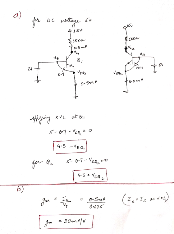


a) A C 10KJレ 0 5mA c2 SV SV 0.1 05mA b) .02S
2- ナ KyL =0
2 CAC
15-0.5m×10K éDC 2- CAC CAC-
L2 AL CAL 2 C2
ラ 200 V 1 V
Know the answer?
Add Answer to:
EXERCISES 8.12 For the circuit in Fig. 8. 19, let 1-1 m1A, Vcc-15 VR-|0 kQ, with α 1, and let the...
Not the answer you're looking for?
Ask your own homework help question.
Our experts will answer your question WITHIN MINUTES for Free.
Similar Homework Help Questions
9.45 For the differential amplifier of Fig. 9.14, let Vcc = +5 V and IRC =...
 9.45 For the differential amplifier of Fig. 9.14, let Vcc = +5 V and IRC = 4 V. Find the differential gain Ag. Sketch and clearly label the waveforms for the total collector voltages vci and vc2 and for (vc2 – Vci) for the case: VR1 = 1+0.005 sin(wt) VB2 = 1 – 0.005 sin(wt) - RE vojia li VCI ic over + VB2 Figure 9.14 The basic BJT differential-pair configuration.
 9.45 For the differential amplifier of Fig. 9.14, let Vcc = +5 V and IRC = 4 V. Find the differential gain Ag. Sketch and clearly label the waveforms for the total collector voltages vci and vc2 and for (vc2 – Vci) for the case: VR1 = 1+0.005 sin(wt) VB2 = 1 – 0.005 sin(wt) - RE vojia li VCI ic over + VB2 Figure 9.14 The basic BJT differential-pair configuration.
ADVERTISEMENT
Need Online Homework Help?
Ask
a QuestionGet Answers For Free
Most questions answered within 3 hours.
Most questions answered within 3 hours.
ADVERTISEMENT
ADVERTISEMENT
Active Questions
-
This is C++ code for parking fee management program
#include <iostream>
#include <iomanip>
using namespace std;...
asked 3 minutes ago -
The free energy change for the following reaction at 25 °C, when
[Sn2+] = 1.17 M...
asked 1 hour ago -
An MNE is this kind of industry when competition in one country
is essentially independent of...
asked 3 hours ago -
. For this set of questions, determine what
proportion of a normal distribution is located betweeneach...
asked 3 hours ago -
A college student is employed as a door-to-door newspaper
salesman. Historical data suggests that the student...
asked 4 hours ago -
MATLAB HW 11 problem using Switch Case and Input commands
Write a script file that calculates...
asked 4 hours ago -
Considering gravitational time dilation, calculate the time that
passes in Earth’s surface while 1 hour passes...
asked 5 hours ago -
Minitab Problem: Take the Lake Hume June rainfall data and find
use the processes outlined in...
asked 6 hours ago -
X Company is trying to decide whether to continue using old
equipment to make Product A...
asked 6 hours ago -
IN PYTHON ONLY !! Program 2: Re-work
program #5 (WeeklyHours) from the previous assignment such that...
asked 6 hours ago -
The average length of time between arrivals at a turnpike
toll-booth is 26 seconds. What is...
asked 8 hours ago -
(a) A piston at 6.1 atm contains a gas that occupies a volume of
3.5 L....
asked 9 hours ago
ADVERTISEMENT