
Homework Answers
Add Answer to:
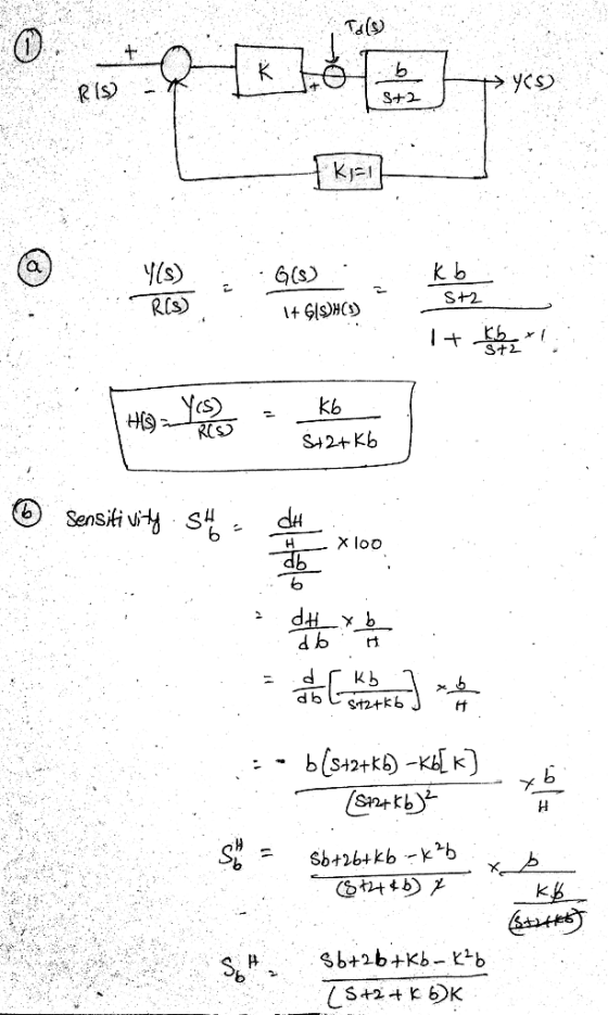
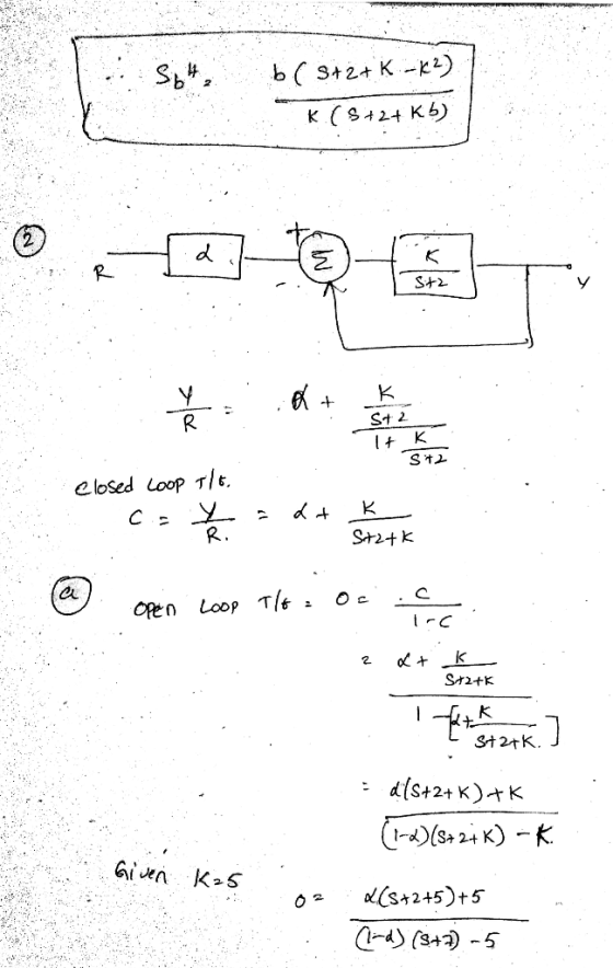
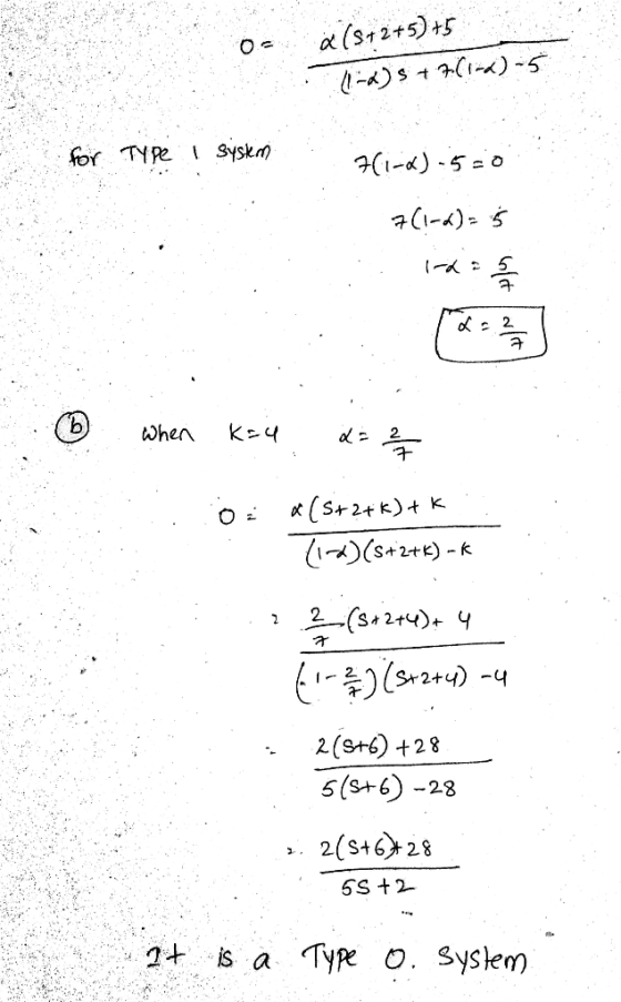
1. (30 points) The block diagram of a machine-tool control system is shown in Figure 1. (a) (10 p...
For the block diagram of a feedback control system that is shown in Figure Q1 below,...
 For the block diagram of a feedback control system that is shown in Figure Q1 below, find the transfer function Ts) Y(s) /R(s) for the system. 2 R(s) Y(s) :? 2 2 Figure Q1
Task: 4 (35 Marks) The block diagram representation of a CNC machine speed control system is...
 Task: 4 (35 Marks) The block diagram representation of a CNC machine speed control system is shown in Figure 4 with the gain of K, and the feedback value of K2. R(s) + cls 100 1 + 0.2s G1=6.5 K1=14.5 K2=0.55 R=3 L=7 C=0.5 Figure 4 (i). Evaluate the closed loop transfer function of the CNC speed control system; (i). Estimate the value of time constant (T) and dc gain K for the CNC speed control system; Note: Each student...
Solve 2.8 Please brake force on each wheel [15].A block diagram model of a brake control system is shown in Figure E...
 Solve 2.8 Please
brake force on each wheel [15].A block diagram model of a brake control system is shown in Figure E2.9, where F(s) and FR(S) are the braking force of the front and rear wheels, respectively, and R(s) is the desired automobile response on an icy road. Find F(s)/R(s) E28 A control engineer, N. Minorsky, designed an inno- vative ship steering system in the 1930s for the US 2 Navy. The system is represented by the block diagram shown...
Solve 2.8 Please
brake force on each wheel [15].A block diagram model of a brake control system is shown in Figure E2.9, where F(s) and FR(S) are the braking force of the front and rear wheels, respectively, and R(s) is the desired automobile response on an icy road. Find F(s)/R(s) E28 A control engineer, N. Minorsky, designed an inno- vative ship steering system in the 1930s for the US 2 Navy. The system is represented by the block diagram shown...
Problem 1 (30 points): A system's block diagram is shown in the figure. 1. Transform the...
 Problem 1 (30 points): A system's block diagram is shown in the figure. 1. Transform the block diagram to an SFG 2. Calculate the transfer function from R(s) to Y)
2. (disturbances & sensitivity) For the control system shown in the figure below, do the following:...
 2. (disturbances & sensitivity) For the control system shown in the figure below, do the following: i. Simplify the block diagram to form a negative unity feedback system ii. Determine the system type. ii. Find the steady-state error for r(t) 2tu(t) and d(t) 0 iv. Find the steady-state error for r(t) 0 and d(t) -0.2ut) v. Find the total error to both the input and the disturbance vi. Find the sensitivity of the total steady-state error to changes in Ki...
Question 8 1 pts Figure 5.42 Controller Process G (s) Y(s) R(s) G(s) Block diagram for...
 Question 8 1 pts Figure 5.42 Controller Process G (s) Y(s) R(s) G(s) Block diagram for the Skills Check. Consider the block diagram of the control system shown in Figure 5.42 in Problems 8 and 9 with the loop transfer function K L(s) G,(s)G(s) s(s+10) Find the value of K so that the system provides an optimum ITAE response. OK= 1.10 K 12.56 K= 51.02 K = 104.7
Question 8 1 pts Figure 5.42 Controller Process G (s) Y(s) R(s)...
Question 8 1 pts Figure 5.42 Controller Process G (s) Y(s) R(s) G(s) Block diagram for the Skills Check. Consider the block diagram of the control system shown in Figure 5.42 in Problems 8 and 9 with the loop transfer function K L(s) G,(s)G(s) s(s+10) Find the value of K so that the system provides an optimum ITAE response. OK= 1.10 K 12.56 K= 51.02 K = 104.7
Question 8 1 pts Figure 5.42 Controller Process G (s) Y(s) R(s)...
1- Consider the block diagram of a control system shown in Fig. 1 Rts) E ts) C(s) Gt-11027 20s Fi...
 1- Consider the block diagram of a control system shown in Fig. 1 Rts) E ts) C(s) Gt-11027 20s Fig. 1 a) Find the open-loop transfer function of the system. b) Determine the system type and open-loop gain in terms of K and K, c) Find the steady-state errors of the system in terms of K and K,when the following reference inputs are applied: a. Unit ramp reference input: ) b. Parabolic reference input: r()
1- Consider the block diagram...
1- Consider the block diagram of a control system shown in Fig. 1 Rts) E ts) C(s) Gt-11027 20s Fig. 1 a) Find the open-loop transfer function of the system. b) Determine the system type and open-loop gain in terms of K and K, c) Find the steady-state errors of the system in terms of K and K,when the following reference inputs are applied: a. Unit ramp reference input: ) b. Parabolic reference input: r()
1- Consider the block diagram...
QI. The block diagram representing a mechanical system is shown in Figure 1(a). The desired set...
 QI. The block diagram representing a mechanical system is shown in Figure 1(a). The desired set point to controllers is r(t) = 50. The system vibrates as shown in Figure 1(b). (1) Find the transfer function of C(s) /R(s) by reducing the block diagram (in) Determine the value of a and b (ii) Find the steady state error of the system Figure 1(a) Time (seconds) Figure 1(b) ANSWER Transfer function, 0.12b +0.12 0.12as +012bs + 0.125 + 1 () Mp....
5. A block diagram of a control system is shown in Figure 3. [10 marks] (a)...
 5. A block diagram of a control system is shown in Figure 3. [10 marks] (a) Find the transfer function of the control system. (b) Assign three poles of the system to -6, -8 and -7 by using time domain full-state feedback control design techniques. 10 marks] 10 15
In the block diagram of the feedback control system shown in figure below, Gp(s) is the...
 In the block diagram of the feedback control system shown in figure below, Gp(s) is the transfer function of a process, R(s) is reference input, and A(s) and H(s) represent controllers. N(S) R(s) Gp(s) Process A(s) H(s) = _100_ , and H(s)-1 / GAS). Let Gs)-A(S)5.and Find the steady state value of the response C(t), when N(t) = R(t) = unit-step function. Is this also the maximum value attained by the response? Justify your answers. (s2+2s+4)
 For the block diagram of a feedback control system that is shown in Figure Q1 below, find the transfer function Ts) Y(s) /R(s) for the system. 2 R(s) Y(s) :? 2 2 Figure Q1
 Task: 4 (35 Marks) The block diagram representation of a CNC machine speed control system is shown in Figure 4 with the gain of K, and the feedback value of K2. R(s) + cls 100 1 + 0.2s G1=6.5 K1=14.5 K2=0.55 R=3 L=7 C=0.5 Figure 4 (i). Evaluate the closed loop transfer function of the CNC speed control system; (i). Estimate the value of time constant (T) and dc gain K for the CNC speed control system; Note: Each student...
 Solve 2.8 Please
brake force on each wheel [15].A block diagram model of a brake control system is shown in Figure E2.9, where F(s) and FR(S) are the braking force of the front and rear wheels, respectively, and R(s) is the desired automobile response on an icy road. Find F(s)/R(s) E28 A control engineer, N. Minorsky, designed an inno- vative ship steering system in the 1930s for the US 2 Navy. The system is represented by the block diagram shown...
Solve 2.8 Please
brake force on each wheel [15].A block diagram model of a brake control system is shown in Figure E2.9, where F(s) and FR(S) are the braking force of the front and rear wheels, respectively, and R(s) is the desired automobile response on an icy road. Find F(s)/R(s) E28 A control engineer, N. Minorsky, designed an inno- vative ship steering system in the 1930s for the US 2 Navy. The system is represented by the block diagram shown...
 Problem 1 (30 points): A system's block diagram is shown in the figure. 1. Transform the block diagram to an SFG 2. Calculate the transfer function from R(s) to Y)
 2. (disturbances & sensitivity) For the control system shown in the figure below, do the following: i. Simplify the block diagram to form a negative unity feedback system ii. Determine the system type. ii. Find the steady-state error for r(t) 2tu(t) and d(t) 0 iv. Find the steady-state error for r(t) 0 and d(t) -0.2ut) v. Find the total error to both the input and the disturbance vi. Find the sensitivity of the total steady-state error to changes in Ki...
 Question 8 1 pts Figure 5.42 Controller Process G (s) Y(s) R(s) G(s) Block diagram for the Skills Check. Consider the block diagram of the control system shown in Figure 5.42 in Problems 8 and 9 with the loop transfer function K L(s) G,(s)G(s) s(s+10) Find the value of K so that the system provides an optimum ITAE response. OK= 1.10 K 12.56 K= 51.02 K = 104.7
Question 8 1 pts Figure 5.42 Controller Process G (s) Y(s) R(s)...
Question 8 1 pts Figure 5.42 Controller Process G (s) Y(s) R(s) G(s) Block diagram for the Skills Check. Consider the block diagram of the control system shown in Figure 5.42 in Problems 8 and 9 with the loop transfer function K L(s) G,(s)G(s) s(s+10) Find the value of K so that the system provides an optimum ITAE response. OK= 1.10 K 12.56 K= 51.02 K = 104.7
Question 8 1 pts Figure 5.42 Controller Process G (s) Y(s) R(s)...
 1- Consider the block diagram of a control system shown in Fig. 1 Rts) E ts) C(s) Gt-11027 20s Fig. 1 a) Find the open-loop transfer function of the system. b) Determine the system type and open-loop gain in terms of K and K, c) Find the steady-state errors of the system in terms of K and K,when the following reference inputs are applied: a. Unit ramp reference input: ) b. Parabolic reference input: r()
1- Consider the block diagram...
1- Consider the block diagram of a control system shown in Fig. 1 Rts) E ts) C(s) Gt-11027 20s Fig. 1 a) Find the open-loop transfer function of the system. b) Determine the system type and open-loop gain in terms of K and K, c) Find the steady-state errors of the system in terms of K and K,when the following reference inputs are applied: a. Unit ramp reference input: ) b. Parabolic reference input: r()
1- Consider the block diagram...
 QI. The block diagram representing a mechanical system is shown in Figure 1(a). The desired set point to controllers is r(t) = 50. The system vibrates as shown in Figure 1(b). (1) Find the transfer function of C(s) /R(s) by reducing the block diagram (in) Determine the value of a and b (ii) Find the steady state error of the system Figure 1(a) Time (seconds) Figure 1(b) ANSWER Transfer function, 0.12b +0.12 0.12as +012bs + 0.125 + 1 () Mp....
 5. A block diagram of a control system is shown in Figure 3. [10 marks] (a) Find the transfer function of the control system. (b) Assign three poles of the system to -6, -8 and -7 by using time domain full-state feedback control design techniques. 10 marks] 10 15
 In the block diagram of the feedback control system shown in figure below, Gp(s) is the transfer function of a process, R(s) is reference input, and A(s) and H(s) represent controllers. N(S) R(s) Gp(s) Process A(s) H(s) = _100_ , and H(s)-1 / GAS). Let Gs)-A(S)5.and Find the steady state value of the response C(t), when N(t) = R(t) = unit-step function. Is this also the maximum value attained by the response? Justify your answers. (s2+2s+4)
Most questions answered within 3 hours.
-
In a certain binary-star system, each star has the same mass
which is 4.4 times of...
asked 1 minute ago -
Use the model of the small open economy (Apply the small
open economy model of real...
asked 8 minutes ago -
The structure Car is declared as follows: struct Car { string
carMake; string carModel; int yearModel;...
asked 17 minutes ago -
Consider a transformer with 125 turns of wire in the primary
winding and 1475 turns of...
asked 18 minutes ago -
Let h be the depth below the surface of the ocean at which the
absolute pressure...
asked 20 minutes ago -
Apply the four-stage New Product Development model shown in page
325 of your text book
(Concept...
asked 28 minutes ago -
An enzyme catalyzes the reaction A ⇌ B. The enzyme is present at
a concentration of...
asked 36 minutes ago -
The number of years of education of self-employed individuals in
the United States has a population...
asked 1 hour ago -
Using the TI-84 calculator, find the area under the standard
normal curve that lies outside the...
asked 51 minutes ago -
You are considering the purchase of a share of Edie's common
stock. You expect to sell...
asked 53 minutes ago -
Assembly Programming
INCLUDE Irvine32.inc
Make a program that takes a string and a word as inputs...
asked 1 hour ago -
Can I get a C++ code and output for this program using classes
instead of using...
asked 1 hour ago